50
SETUP INPUT (Settings specific to each of the 12 Input Select Buttons)
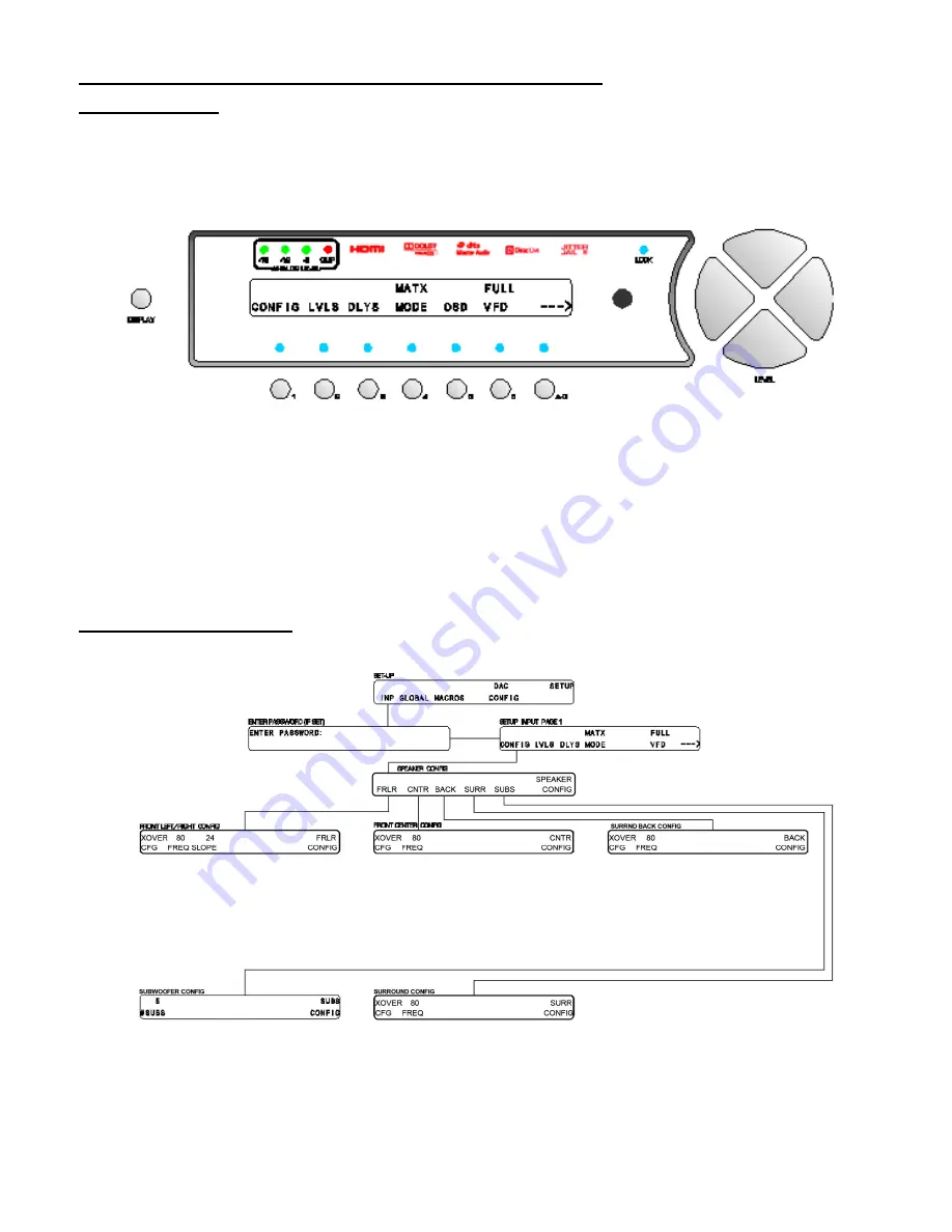
Setup Input Page 1
All parameters accessed within the
SETUP/INP
menu are separately programmable for each of the 12
INPUT SELECT
buttons.
From the
SETUP
menu press button #
1
(
INP
). The first of three pages of the
SETUP
/
INPUT
submenus will appear, as
shown in figure 22.
Figure 22 - Front Panel Display of the SETUP
/
INPUT page 1 Submenu
Pressing button #
1
takes the user into a series of submenus that allow the configuration of all speakers. Button #
2
allows the user to set the speaker levels and button #
3
allows the user to set speaker delays.
Press button #
4
and use the
LEVEL
UP
/
DOWN
buttons to set the default
MODE
for the currently selected
INPUT
SELECT
button.
Button #
6
provides a means of setting the VFD brightness for the currently selected
INPUT SELECT
button.
Pressing the
A-D
button takes the user to page 2 of
SETUP
/
INP
.
Setup Speaker Configuration
The Speaker Configuration section utilizes the menus shown in figure 23.
Figure 23 - Menu Map of SETUP/INP
Page 1
/CONFIG
The configuration submenus (
CONFIG)
allow the user to configure the Casablanca IV to reflect the audio system
configuration or the listener’s preference for the available speakers and their respective frequency responses.
Summary of Contents for Casablanca IV
Page 2: ...THETA DIGITAL Casablanca IV Owner s Manual V 4 02 Digital Done Right...
Page 17: ...16 Figure 8 All Superior II D A Card Options...
Page 20: ...19...
Page 22: ...21...
Page 31: ...30 Flowchart A Setup Subwoofer s...
Page 32: ...31 Flowchart B Front Left Right Configuration...
Page 33: ...32...
Page 35: ...34 Flowchart F Setup Speaker Levels...
Page 36: ...35 Flowchart H Setup Speaker Delays...
Page 37: ...36 Flowchart I Setup Dolby Digital...
Page 38: ...37 Flowchart J Setup DTS For 7 1 system Set additional Speaker Process Step 13h...
Page 39: ...38 Flowchart K Copy Input Speaker Parameters...
Page 40: ...39 Flowchart L Setup Default Mode...
Page 41: ...40 Flowchart M Map Input Jacks...
Page 42: ...41 Flowchart N Setup Analog Input Levels...
Page 80: ...79 REMOTE CONTROL...
Page 81: ...80 Figure 59 Remote Control Button Layout...
Page 85: ...84 APPENDIXES...
Page 88: ...87 Figure 62 Recommended Output Wiring Diagram Using 8 balanced Xtreme channels...
Page 89: ...88 Six Shooter Wiring Diagram Figure 63 Wiring diagram for the optional Six Shooter...


