53
Left/Right Speaker Configuration
The left/right configuration section contains the submenus shown in figure 23.
Figure 26 - Menu Map of SETUP/INP
Page 1
/CONFIG/LT/RT
A discussion of crossovers commences on page 25.
Crossovers
The Casablanca IV contains Linkwitz-Riley crossover filters. Combined with knowledge of the actual in-room frequency
response of each speaker in the system as measured by Theta Digital’s Dirac Live® 96 kHz module, the end results can
offer state-of-the-art performance..
* * *
Press button #
1
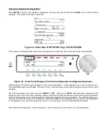
to set up the front left/right speakers. This configuration submenu is shown in figure 27.
Figure 27 - Front Panel Display of the Front Left/Right Speaker Configuration
Submenu
Pressing button #
1
allows the configuration of the front left/right speakers. If these speakers are not to be crossed over
(a portion of their signal sent to the
SUB
output(s)), then the setting should be
FULL
.
Should it be desired to crossover the front left/right speakers, the
CFG
setting (button #
1
) should be set to
XOVER.
FREQ
can be configured for any frequency from 40 Hz to 220 Hz in 10 Hz increments. 80 Hz is the default. Consult
the specification sheet for the loudspeakers being used or, preferably, the in-room frequency response measured during
Dirac Live® to determine the appropriate crossover frequency.
SLOPE refers to the subwoofer channel’s low pass filter. The choices are 12 or 24. The default setting is 24 and
is usually the appropriate selection.
Summary of Contents for Casablanca IV
Page 2: ...THETA DIGITAL Casablanca IV Owner s Manual V 4 02 Digital Done Right...
Page 17: ...16 Figure 8 All Superior II D A Card Options...
Page 20: ...19...
Page 22: ...21...
Page 31: ...30 Flowchart A Setup Subwoofer s...
Page 32: ...31 Flowchart B Front Left Right Configuration...
Page 33: ...32...
Page 35: ...34 Flowchart F Setup Speaker Levels...
Page 36: ...35 Flowchart H Setup Speaker Delays...
Page 37: ...36 Flowchart I Setup Dolby Digital...
Page 38: ...37 Flowchart J Setup DTS For 7 1 system Set additional Speaker Process Step 13h...
Page 39: ...38 Flowchart K Copy Input Speaker Parameters...
Page 40: ...39 Flowchart L Setup Default Mode...
Page 41: ...40 Flowchart M Map Input Jacks...
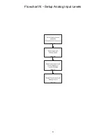
Page 42: ...41 Flowchart N Setup Analog Input Levels...
Page 80: ...79 REMOTE CONTROL...
Page 81: ...80 Figure 59 Remote Control Button Layout...
Page 85: ...84 APPENDIXES...
Page 88: ...87 Figure 62 Recommended Output Wiring Diagram Using 8 balanced Xtreme channels...
Page 89: ...88 Six Shooter Wiring Diagram Figure 63 Wiring diagram for the optional Six Shooter...


