56
Surround Speaker Configuration
Press
SETUP
to return to the speaker configuration submenu, then press button #
4
(
SURR
) to set up the surround
speakers. This submenu is shown in figure 32.
Figure 32 - Menu Map of SETUP/INP
Page 1
/CONFIG/SURR
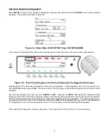
This submenu of settings for the back surround speakers is virtually the same as the one for the center speaker.
Figure 33 - Front Panel Display of the Surround Speaker Configuration Submenu
Pressing button #
1
allows the configuration of the surround speakers. If these speakers are not to be crossed over,
then the
CFG
should be set to
FULL
. When set to FULL, the full range surround channel signal is sent to the surround
speakers.
The surround speakers can also be set to
XOVER
or
OFF
. When set to
XOVR
, bass below the requested cutoff
frequency will be sent to the other speakers capable of reproducing those frequencies including the surround speakers,
the front L/R speakers and/or the Subwoofer(s) depending upon their selected capabilities. The cutoff frequency may
be set from 40 Hz to 220 Hz in 10 Hz increments. When set to
OFF
, of if the speakers are not present in the Casablanca
IV configuration menu, the channel signal is not lost. It is sent equally to the Left and Right front speakers.
Press button #
2
to adjust the crossover frequency. The choices are 40 Hz to 220 Hz in 10 Hz increments.
Summary of Contents for Casablanca IV
Page 2: ...THETA DIGITAL Casablanca IV Owner s Manual V 4 02 Digital Done Right...
Page 17: ...16 Figure 8 All Superior II D A Card Options...
Page 20: ...19...
Page 22: ...21...
Page 31: ...30 Flowchart A Setup Subwoofer s...
Page 32: ...31 Flowchart B Front Left Right Configuration...
Page 33: ...32...
Page 35: ...34 Flowchart F Setup Speaker Levels...
Page 36: ...35 Flowchart H Setup Speaker Delays...
Page 37: ...36 Flowchart I Setup Dolby Digital...
Page 38: ...37 Flowchart J Setup DTS For 7 1 system Set additional Speaker Process Step 13h...
Page 39: ...38 Flowchart K Copy Input Speaker Parameters...
Page 40: ...39 Flowchart L Setup Default Mode...
Page 41: ...40 Flowchart M Map Input Jacks...
Page 42: ...41 Flowchart N Setup Analog Input Levels...
Page 80: ...79 REMOTE CONTROL...
Page 81: ...80 Figure 59 Remote Control Button Layout...
Page 85: ...84 APPENDIXES...
Page 88: ...87 Figure 62 Recommended Output Wiring Diagram Using 8 balanced Xtreme channels...
Page 89: ...88 Six Shooter Wiring Diagram Figure 63 Wiring diagram for the optional Six Shooter...


