v
SAFETY PRECAUTIONS
Please carefully read each item of the operating instructions and safety precautions before using this product.
Use extra care to follow the warnings written on the product itself and/or in the operating instructions. Keep
the operating instructions and safety precautions for future reference.
CAUTION: TO REDUCE THE RISK OF ELECTRICAL SHOCK, DO NOT REMOVE ANY OF THE COVER
PANELS.
NO USER-SERVICEABLE PARTS INSIDE. REFER ALL SERVICING TO QUALIFIED SERVICE
PERSONNEL ONLY.
TO PREVENT FIRE OR SHOCK HAZARD, DO NOT ALLOW LIQUIDS TO SPILL OR OBJECTS TO FALL
INTO ANY OPENINGS OF THE PRODUCT.
THIS UNIT IS SUPPLIED WITH A 3 PIN GROUNDED AC PLUG. ALWAYS INSERT THE AC PLUG INTO A
GROUNDED OUTLET. DO NOT REMOVE THE GROUND PIN OR DISABLE THE GROUND FOR ANY
PURPOSE.
BEFORE MAKING ANY CONNECTIONS TO THE CASABLANCA IV, FIRST TURN OFF THE POWER AND
THEN DISCONNECT THE AC POWER CORD.
WHEN INSTALLING THE CASABLANCA IV IN YOUR SYSTEM, MAKE CERTAIN TO ALLOW A MINIMUM
OF 3 INCHS OF VENTILATION ON EACH SIDE OF THE UNIT. ALSO ALLOW AT LEAST 4 INCHS OF
VENTILATION SPACE ABOVE THE UNIT. IMPROPER VENTILATION OF THE UNIT MAY CAUSE
OVERHEATING, WHICH MAY DAMAGE THE UNIT AND CAUSE A FIRE. PLACE THE UNIT ON A SOLID
SURFACE ONLY. I.E. NOT ON CARPET, ETC.
DO NOT PLACE THE CASABLANCA IV NEAR HEAT SOURCES SUCH AS DIRECT SUNLIGHT, STOVES,
HEAT REGISTERS, RADIATORS OR OTHER HEAT PRODUCING EQUIPMENT.
TO PREVENT DAMAGE TO THE ANALOG OUTPUT CIRCUITRY, BE CERTAIN NOT TO SHORT THE
OUTPUT SIGNAL PIN(S) TO GROUND. ENSURE THAT YOUR AUDIO OUTPUT CABLES DO NOT HAVE
ANY INTERNAL SHORTS BEFORE CONNECTING THEM TO THE CASABLANCA IV.
IF REPLACEMENT OF THE AC LINE FUSE BECOMES NECESSARY, REPLACE ONLY WITH SAME
VALUE AND TYPE OF FUSE. NEVER BYPASS THE FUSE.
IF THE AC CORD BECOMES DAMAGED, DO NOT USE IT. IMMEDIATELY REPLACE IT WITH A NEW
ONE OF THE SAME OR BETTER RATING.
AFTER MARKET and THIRD PARTY MODIFICATIONS
Please note that any aftermarket and/or third party modifications will void the warranty. In the case of changing
the feet on a unit, in order to prevent any damage (which will also not be covered under warranty), please
verify that the screws being used to secure non Casablanca IV feet do not screw any deeper into the chassis
than the original ones. The original screw is 10-32 by 3/8 and goes into the chassis 1/5 inch.
Summary of Contents for Casablanca IV
Page 2: ...THETA DIGITAL Casablanca IV Owner s Manual V 4 02 Digital Done Right...
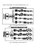
Page 17: ...16 Figure 8 All Superior II D A Card Options...
Page 20: ...19...
Page 22: ...21...
Page 31: ...30 Flowchart A Setup Subwoofer s...
Page 32: ...31 Flowchart B Front Left Right Configuration...
Page 33: ...32...
Page 35: ...34 Flowchart F Setup Speaker Levels...
Page 36: ...35 Flowchart H Setup Speaker Delays...
Page 37: ...36 Flowchart I Setup Dolby Digital...
Page 38: ...37 Flowchart J Setup DTS For 7 1 system Set additional Speaker Process Step 13h...
Page 39: ...38 Flowchart K Copy Input Speaker Parameters...
Page 40: ...39 Flowchart L Setup Default Mode...
Page 41: ...40 Flowchart M Map Input Jacks...
Page 42: ...41 Flowchart N Setup Analog Input Levels...
Page 80: ...79 REMOTE CONTROL...
Page 81: ...80 Figure 59 Remote Control Button Layout...
Page 85: ...84 APPENDIXES...
Page 88: ...87 Figure 62 Recommended Output Wiring Diagram Using 8 balanced Xtreme channels...
Page 89: ...88 Six Shooter Wiring Diagram Figure 63 Wiring diagram for the optional Six Shooter...

