62
Setup Dolby Digital
In figure 40, button #
2
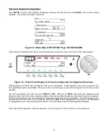
provides a two-page submenu which allows the user to set up preferences pertaining to Dolby
Digital and Dolby Pro Logic IIx, by
INPUT SELECT
button. The first page of this submenu is shown in figure 41. These
settings apply only when the
MODE
is one of the Dolby Digital processes.
Figure 41 - Front Panel Display of the SETUP
/
INP
Page 2
/
DOLBY DIGITAL
Page 1
Submenu
2-Channel Mode
Some Dolby Digital sources contain only two of the possible five to seven main channels. This is usually noted on the
material's cover, in the form of "Dolby Digital 2.0" or “Dolby Surround” as opposed to "Dolby Digital 5.1, 6.1 or 7.1".
Embedded in most two-channel Dolby Digital data streams is an indication of whether or not the material is Dolby
Surround encoded. There are three possibilities for this indication: Dolby Surround Encoded; Not Dolby Surround
Encoded; or No Indication.
Regardless of the indication, the user can instruct the Casablanca IV to process this decoded signal in virtually any
MODE
. For Dolby Surround encoded signals, press button #
1
(
2CHEN
– or two-channel encoded) and use the LEVEL
UP/DOWN buttons to select the
MODE
to be applied to Encoded 2 channel Dolby Digital signals. For a non-encoded
signal, press button #
2
(
2CHNEN
– or 2-channel non-encoded) to select the
MODE
for further processing. When a
mode is applied to a two-channel Dolby Digital signal, the signal Is first Dolby Digital decoded, then the decoded signal
is further manipulated by applying the mode set in the
2CHEN
or
2CHNEN
parameters. If this is the case, and the
additional selected mode is
MATRIX
, the
MODE
displayed in the VFD when in the
INPUT SELECT MENU
will read
“
DOLBY D MATX
”. If the additional selected mode is
STEREO
, the
MODE
displayed in the VFD when in the
INPUT SELECT MENU
will read “
DOLBY D STEREO
”.
If the indication is that the signal is not Dolby Surround encoded, or there is no indication, and the
2CHNEN
MODE
is
set to Dolby Digital, no additional surround processing will occur, resulting in a two-channel (stereo) output.
Compression
(Night Mode)
Dolby Digital contains provisions for reducing the dynamic range of a Dolby Digital source. This means reducing the
loudness of the loud passages and increasing the loudness of the quiet passages. Possible reasons for reducing the
dynamic range of a source include late night listening wherein loud moments may disturb others, and making tapes for
automotive / portable use wherein quiet passages may not be heard.
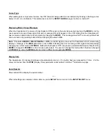
Casablanca IV contains three parameters to control Dolby Digital compression. Button #
3
(
CMP
) turns the compression
ON
or
OFF
. Button #
4
(
HCMP
, or High Compression) controls the degree to which loud passages will be reduced.
Button #
5
(
LCMP
, or Low Compression) controls the degree to which quiet passages will be increased.
Note
: Some Dolby Digital sources do not allow for compression, in which case altering these settings will have no effect.
Press button #6 to select the processing for additional speakers when the
MODE
is Dolby Digital.
If the incoming signal is Dolby Digital 5.1, and the user desires to create Surround Back channel, use the
+SPKR
(or
Additional Speakers) parameter to indicate which
MODE
will be used to create them. There are a limited number of
Summary of Contents for Casablanca IV
Page 2: ...THETA DIGITAL Casablanca IV Owner s Manual V 4 02 Digital Done Right...
Page 17: ...16 Figure 8 All Superior II D A Card Options...
Page 20: ...19...
Page 22: ...21...
Page 31: ...30 Flowchart A Setup Subwoofer s...
Page 32: ...31 Flowchart B Front Left Right Configuration...
Page 33: ...32...
Page 35: ...34 Flowchart F Setup Speaker Levels...
Page 36: ...35 Flowchart H Setup Speaker Delays...
Page 37: ...36 Flowchart I Setup Dolby Digital...
Page 38: ...37 Flowchart J Setup DTS For 7 1 system Set additional Speaker Process Step 13h...
Page 39: ...38 Flowchart K Copy Input Speaker Parameters...
Page 40: ...39 Flowchart L Setup Default Mode...
Page 41: ...40 Flowchart M Map Input Jacks...
Page 42: ...41 Flowchart N Setup Analog Input Levels...
Page 80: ...79 REMOTE CONTROL...
Page 81: ...80 Figure 59 Remote Control Button Layout...
Page 85: ...84 APPENDIXES...
Page 88: ...87 Figure 62 Recommended Output Wiring Diagram Using 8 balanced Xtreme channels...
Page 89: ...88 Six Shooter Wiring Diagram Figure 63 Wiring diagram for the optional Six Shooter...


