68
Setup Miscellaneous
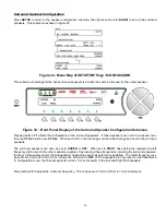
Press
Button #7, (Figure 40
)
to enter the
MISC
submenu, shown in figure 45.
Figure 45 - Front Panel Display of the SETUP
/
INP
page 3
/
MISC Submenu
Naming the Current Input Select button
This parameter sets the name (VFD) for the currently selected input. Select the input to rename. The letters
VFD
will
be displayed in the lower right above the
A-D
button, indicating that the name in the VFD is to be edited. VFD names
are limited to 4 characters. Press the
LEVEL UP
/
DOWN
button to change characters and the
LEVEL LEFT
/
RIGHT
to
change character positions. Pressing the
DISPLAY
button once will clear the current
INPUT SELECT
name. Press
SETUP
once to return to the
SETUP
/
INP
page 3
submenu.
Turning Dirac Live® 96 kHz On and Off
This parameter turns Dirac Live 96® kHz Room Correction and Optimization on or off and selects which of the two filter
banks. A or B, should be used for Dirac playback.
Currently only Filter A is enabled on the Casablanca IV.
Turning Jitter Jail™ II On and Off
This parameter turns on Theta Digital’s proprietary Jitter Jail II time correction circuitry. Jitter and its attendant distortion
is caused by timing errors in the digital data stream. Jitter Jail II engages a precision playback clock to reduce any such
distortion to below audible levels.
Summary of Contents for Casablanca IV
Page 2: ...THETA DIGITAL Casablanca IV Owner s Manual V 4 02 Digital Done Right...
Page 17: ...16 Figure 8 All Superior II D A Card Options...
Page 20: ...19...
Page 22: ...21...
Page 31: ...30 Flowchart A Setup Subwoofer s...
Page 32: ...31 Flowchart B Front Left Right Configuration...
Page 33: ...32...
Page 35: ...34 Flowchart F Setup Speaker Levels...
Page 36: ...35 Flowchart H Setup Speaker Delays...
Page 37: ...36 Flowchart I Setup Dolby Digital...
Page 38: ...37 Flowchart J Setup DTS For 7 1 system Set additional Speaker Process Step 13h...
Page 39: ...38 Flowchart K Copy Input Speaker Parameters...
Page 40: ...39 Flowchart L Setup Default Mode...
Page 41: ...40 Flowchart M Map Input Jacks...
Page 42: ...41 Flowchart N Setup Analog Input Levels...
Page 80: ...79 REMOTE CONTROL...
Page 81: ...80 Figure 59 Remote Control Button Layout...
Page 85: ...84 APPENDIXES...
Page 88: ...87 Figure 62 Recommended Output Wiring Diagram Using 8 balanced Xtreme channels...
Page 89: ...88 Six Shooter Wiring Diagram Figure 63 Wiring diagram for the optional Six Shooter...


