69
Setup Global
This function provides access to a series of submenus that will allow the configuration of the entire system (not by input).
Press
SETUP
, then
GLOBAL
(button #
2
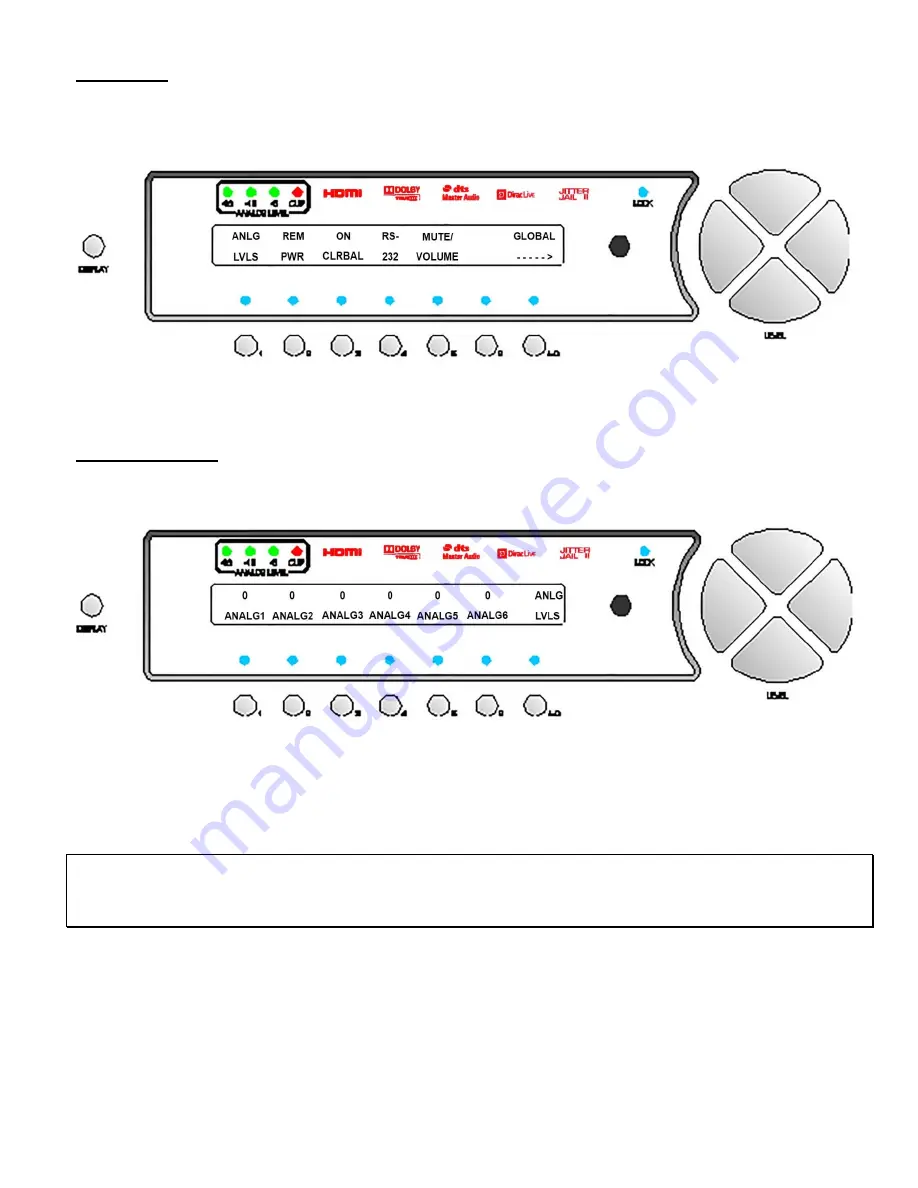
). The first page of the Global submenu is displayed, as shown in figure 46.
Figure 46 - Front Panel Display of the SETUP
/
GLOBAL
page 1
/
Submenu
Analog Input Levels
From the
SETUP
/
GLOBAL
page
1
menu, press button #
1
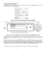
to bring up a submenu that allows adjustment of the analog
input levels. This submenu is shown in figure 47.
Figure 47 - Front Panel Display of the SETUP
/
GLOBAL
/
ANLG LVLS Submenu
This function allows the user to adjust the relative
ANALOG
input
LEVEL
for each input source, for those modes which
require analog to digital conversion. The allowable relative range is +19 to -14dB in 1dB increments, then steps to -16,
-18 and -22dB.
Note
: To obtain the best performance from the analog to digital conversion process, levels should be set so that the
loudest passages from the source material cause the
-18
,
-12
and
-6
dB
ANALOG
input
LEVEL
LEDs on the front panel
to light. Setting the input level too high will cause all four LEDs to light, thus clipping the input signal and causing
distortion.
Analog output levels may vary considerably for different input sources, but program material from a given input source
should be more relatively consistent. Therefore the
ANALOG
input
LEVEL
for a given source should not have to be
adjusted very often. If the
ANALOG LEVEL
LEDs are not lit during the loudest passages from an analog source, the
user could increase the
ANALOG
input
LEVEL
for that source in order to ensure a good signal to noise ratio. Another
way to do this is in the 2
nd
Balance menu, however it is temporary. If that particular source were recorded at a particularly
high or low level, the analog input level can be temporarily adjusted in the 2
nd
BALANCE
menu
Select the analog input to be adjusted by pressing buttons
1
-
6
. Adjust the relative input level using the
LEVEL UP
/
DOWN
buttons, then press the
SETUP
button three times to return to the current
INPUT SELECT
page.
Summary of Contents for Casablanca IV
Page 2: ...THETA DIGITAL Casablanca IV Owner s Manual V 4 02 Digital Done Right...
Page 17: ...16 Figure 8 All Superior II D A Card Options...
Page 20: ...19...
Page 22: ...21...
Page 31: ...30 Flowchart A Setup Subwoofer s...
Page 32: ...31 Flowchart B Front Left Right Configuration...
Page 33: ...32...
Page 35: ...34 Flowchart F Setup Speaker Levels...
Page 36: ...35 Flowchart H Setup Speaker Delays...
Page 37: ...36 Flowchart I Setup Dolby Digital...
Page 38: ...37 Flowchart J Setup DTS For 7 1 system Set additional Speaker Process Step 13h...
Page 39: ...38 Flowchart K Copy Input Speaker Parameters...
Page 40: ...39 Flowchart L Setup Default Mode...
Page 41: ...40 Flowchart M Map Input Jacks...
Page 42: ...41 Flowchart N Setup Analog Input Levels...
Page 80: ...79 REMOTE CONTROL...
Page 81: ...80 Figure 59 Remote Control Button Layout...
Page 85: ...84 APPENDIXES...
Page 88: ...87 Figure 62 Recommended Output Wiring Diagram Using 8 balanced Xtreme channels...
Page 89: ...88 Six Shooter Wiring Diagram Figure 63 Wiring diagram for the optional Six Shooter...


