background image


13 

SERVICING 


We recommend an annual service by an authorised service agent to maintain efficient 
appliance performance. To arrange service, please contact your authorised local Service 
Agent giving full details of the model, serial number and date of purchase. 


Manufactured by: 

THETFORD Limited, 

Unit 6 Brookfields Way, 

Manvers, 

Rotherham, 

S63 5DL, 

UK. 


Service Instructions 


1.  Disconnect from gas and electricity supply 

Lift and remove the bottom plinth to gain access, and then disconnect the gas supply. 
If the appliance is Dual Fuel, the electric supply must be disconnected.


2.  Remove hob surface 

Isolate and disconnect from gas supply and electricity supply if Dual Fuel. Lift off the 
Panrest and remove the two screws securing each burner spreader. Remove front 
fascia by removing all push on control knobs and unscrew the two recessed fixed nuts 
and both fascia retaining screws. Carefully lift off the fascia and if spark ignition fitted 
remove the two spade connectors from the rear of the toggle switch. Remove the two 
central screws securing the pressing to the rear box section. Remove the two front 
retaining screws located each side and accessed through the outer slots on the angled 
front. Grasp the hob by the angled front face; carefully lift the hob surface from the front 
to allow the rear edge to unhook from the rear box section.  Note: - On Dual Fuel 
appliances, remove the hotplate rear cover and disconnect the power leads. The hob 
surface should be placed onto a suitably protected surface.


3.  Remove appliance from housing 

Disconnect from gas and electric supply. Open the oven door and remove the 2 screws 
from each side trim - note the appliance can either be front or side fixed, see under 

Fixing, 

page 13. Open the glass lid and remove the 2 screws from each side trim. 

Carefully slide the appliance out one third and check for any possible snagging of wires 
or pipes. If the appliance is Dual Fuel, disconnect supply lead from rear terminal block. If 
OK, lift appliance out onto a suitable surface. 


  Shut off gas supply at isolating valve and ensure all parts are cool before 

cleaning or servicing 

  All servicing must be carried out by an approved competent person. 

  After each service the appliance must be checked for gas soundness 

  Do not modify this appliance. 

  No parts other than those supplied by the manufacturer should be used on 

this appliance. 


Summary of Contents for SOH70 Z Series

Page 1: ...omerton VIC 3062 TEL 03 9358 0700 FAX 03 9357 7060 MODELS SOH70XXXZ TRIPLEX ALL GAS SOH71XXXZ TRIPLEX DUAL FUEL SOH76XXXZ TRIPLEX WIDE ALL GAS SOH76XXXZ TRIPLEX PLUS ALL GAS SOH77XXXZ TRIPLEX PLUS DUA...

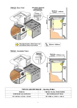
Page 2: ...2 TRIPLEX COOKER RANGE Opening Widths TRIPLEX TRIPLEX PLUS TRIPLEX WIDE SOH70XXXZ S OH71XXXZ SOH76XXXZ SOH77XXXZ W 445mm 2 0mm 0 0mm W 496mm 2 0mm 0 0mm...

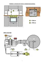
Page 3: ...3 MINIMUM ALLOWABLE DISTANCE TO COMBUSTIBLE MATERIAL WIRING DIAGRAM...

Page 4: ...ODELS WITH COPRECI TAPS SOMIPRESS BURNERS MODEL TRIPLEX PLUS TRIPLEX WIDE TYPE All Gas 4 Burner All Gas 3 Burner CODE SOH76XXXZ SOH76XXXZ DIMENSIONS H W D H mm W mm D Mm H mm W mm D mm 468 513 500 468...

Page 5: ...r adequate air supply for combustion to the burners safe removal of combustion products and avoidance of accumulation of unburned gases Location This appliance maybe installed in a kitchen kitchen din...

Page 6: ...ocedure should be repeated holding the knob depressed for slightly longer 4 For models fitted with Spark Ignition the procedure is similar except that the burner can be ignited by depressing the ignit...

Page 7: ...n to harden and burn off the coating Use a medium to high setting for 3 5 minutes A non toxic smoke may occur during this process Allow it to cool then season To season the Hotplate First heat the hot...

Page 8: ...o help remove the smoke 5 Although the grill does heat up quickly it is recommended that a few minutes preheat be allowed 6 Flame Failure Device FFD the grill burner is fitted with a flame sensing pro...

Page 9: ...helf prevents trays or dishes contacting the back of the oven To remove a shelf pull forward until it stops raise at front and remove Oven Temperature Control The temperature in the oven is controlled...

Page 10: ...e the general area of the leak to be detected Check that the gas is not escaping from an unlit appliance Never check for leaks with a naked flame leak investigation should be carried out using a leak...

Page 11: ...osition CAUTION DO NOT LIFT APPLIANCE USING THE DOOR HANDLES A cut out should be prepared as shown in the enclosed diagrams The cut out MUST comply with the dimensions shown and include the low ventil...

Page 12: ...not be used until the line pressure has been checked The burners on this appliance have fixed aeration and no adjustment is necessary Connection Electrical The appliance is supplied with a power cord...

Page 13: ...on Remove the two front retaining screws located each side and accessed through the outer slots on the angled front Grasp the hob by the angled front face carefully lift the hob surface from the front...

Page 14: ...nd spark ignition probe Trace the electrode wire back to the generator and pull off the connector Oven burner Trace the electrode wire up the back of the cooker to the generator and pull off the conne...

Page 15: ...iscoloured panrest Not a fault Discolouration is unavoidable Chrome panrests are more susceptible to discolouration Burner will not remain lit Thermocouple failure Blocked jet Test replace thermocoupl...

Page 16: ...adjust gas pressure Burner sooting or black marks on rear panel Incorrect combustion Check burner alignment flame should be vertical and not burn against rear panel Burner will not remain lit Thermoc...

Reviews: