OPERATING INSTRUCTIONS
LIFTING POINTS, SCREW TYPE
THIELE GmbH & Co. KG
# Change indicator
www.thiele.de | info@thiele.de
B07905-M
replaces B07905-L
© All rights reserved
EN 07.2021
3 | 6
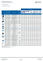
3.2
Technical data for TWN 1830
Nominal WLL
[t]
Article-
No.
Suspension link
[mm]
Thread
d x G
[mm]
Tightenin g
torque
[Nm]
Working Load Limit for each lifting point
depending on alignment and inclination angle
= ± 5°
5° <
≤
105°
5° <
≤
45°
P R E F E R E D
to avoid
[t]
[t]
[t]
0,45
F34306
B13 x 55 x 33
M10 x 15
hand-
screwed
0,9
0,6
0,45
0,6
F34307
B13 x 55 x 33
M12 x 18
1,2
0,75
0,6
1,4
F34300
B13 x 55 x 33
M16 x 20
2,8
1,7
1,4
2,5
F34310
B16 x 70 x 35
M20 x 25
5,3
2,8
2,5
3,5
F34320
B18 x 85 x 40
M24 x 30
7,0
4,0
3,5
5,3
F34330
B22 x 100 x 50
M30 x 40
10
6,3
5,3
8,0
F34340
B22 x 100 x 50
M36 x 50
15
9,5
1)
10
2)
8,0
10
F34350
B32 x 140 x 70
M42 x 60
18
13
10
12,5
F34353
B32 x 140 x 70
M45 x 65
20
15
12,5
12,5
F34355
B32 x 140 x 70
M48 x 68
20
16
12,5
12,5
F34361
#
B32 x 140 x 70
M52 x 78
#
20
16
12,5
17
F34360
B32 x 140 x 70
M56 x 78
28
22
17
17
F34363
B32 x 140 x 70
M64 x 96
28
22
1)
25
2)
17
31,5
F34380
B45 x 220 x 110
M72 x 108
50
40
31,5
35
F34383
B45 x 220 x 110
M80 x 120
50
48
35
40 t
F34385
B45 x 220 x 110
M90 x 135
50
50
40
40 t
F34388
B45 x 220 x 110
M100 x 150
50
50
40
1)
until date of manufacture
„1220“ (De
cember 2020)
2)
from date of manufacture
„0121“ (Januar
y 2021)
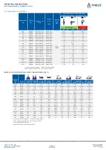
Working Load Limit (WLL) depending on number of legs and inclination angle in t
Nominal
WLL
[t]
Thread
[mm]
1-leg
2- leg
1- leg
2- leg
2- leg
5)
2- leg
5)
3-/4- leg
5)
3-/4- leg
5)
± 5°
± 5°
75- 105°
75- 105°
0°- 45°
45°- 60°
dissym.
6)
0°- 45°
45°- 60°
dissym.
6)
0,45
M10
0,9
1,8
0,6
1,2
0,85
0,6
0,6
1,3
0,9
0,6
0,6
M12
1,2
2,4
0,75
1,5
1,0
0,75
0,75
1,57
1,12
0,75
1,4
M16
2,8
5,6
1,7
3,4
2,4
1,7
1,7
3,6
2,6
1,7
2,5
M20
5,3
10,6
2,8
5,6
4,0
2,8
2,8
5,9
4,2
2,8
3,5
M24
7,0
14
4,0
8,0
5,7
4,0
4,0
8,5
6,0
4,0
5,3
M30
10
20
6,3
12,6
8,9
6,3
6,3
13,4
9,5
6,3
8,0
M36
15
30
9,5
3)
10
4)
19
3)
20
4)
13,4
3)
14,1
4)
9,5
3)
10
4)
9,5
3)
10
4)
20,2
3)
21,2
4)
14,3
3)
15
4)
9,5
3)
10
4)
10
M42
18
36
13
26
18,2
13
13
27,3
19,5
13
12,5
M45
20
40
15
30
21,2
15
15
31,8
22,5
15
12,5
M48
20
40
16
32
22,6
16
16
33,9
24
16
12,5
M52
#
20
40
16
32
22,6
16
16
33,9
24
16
17
M56
28
56
22
44
31,1
22
22
46,7
33
22
17
M64
28
56
22
3)
25
4)
44
3)
50
4)
31,1
3)
35,3
4)
22
3)
25
4)
22
3)
25
4)
46,7
3)
53
4)
33
3)
37,5
4)
22
3)
25
4)
31,5
M72
50
100
40
80
56
40
40
85
60
40
35
M80
50
100
48
96
68
48
48
102
72
48
40
M90
50
100
50
100
71
50
50
106
75
50
40
M100
50
100
50
100
71
50
50
106
75
50
3)
until date of manufacture
„1220“ (De
cember 2020)
4)
from date of manufacture
„0121“ (Januar
y 2021)
5)
for the prefered alignment
6)
Reduced WLL according to DIN 685-5


