OPERATING INSTRUCTIONS
LIFTING POINTS, SCREW TYPE
THIELE GmbH & Co. KG
# Change indicator
www.thiele.de | info@thiele.de
B07905-M
replaces B07905-L
© All rights reserved
EN 07.2021
4 | 6
4
COMMISSIONING
Prior to using the components for the first time make sure that
•
the lifting points comply with the order and have not been damaged,
•
test certificate, statement of compliance, and operating instructions are at hand,
•
markings correspond with what is specified in the documentation,
•
inspection deadlines and the qualified persons for examinations are determined,
•
visibility and functional testing are carried out and documented,
•
documentations are safely kept in an orderly manner.
Dispose of the packing in an environmentally compatible way according to local rules.
5
ASSEMBLY AND REMOVAL
5.1
Preparations
The mounting location for each lifting point must ensure that
•
the load can take the forces safely to be applied without suffering deformation,
•
the lifting point can be assembled flush,
•
no areas of danger are created (crushing point, shearing point),
•
transportation is not restrained by overhang,
•
deflections of sling parts are avoided,
•
incorrect use is avoided,
•
the suspension gear cannot be damaged, for example by sharp edges ,
•
the lifting point can be used easily.
5.2
Assembly
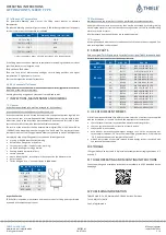
The useful depth of the thread must enable the lifting points to be safely screwed in.
Use only the delivered screws!
Make sure the tapped hole is arranged at right angle to the attachment face on the
component. The depth of
the thread „L“
of the component must at least be as follows:
L = 1,0 x d for steel
L = 1,25 x d for castings
L = 2,0 x d for aluminum
L = 2,5 x d in aluminum-magnesium-alloys
(L = depth of thread; d = thread diameter)
•
Make sure the threads of the lifting point and in the
component are clean and dry.
•
If lifting points should remain on the component a thread
locker has to be used.
•
In case of a bolted joint the nut must be secured against unintentionally loosening.
•
TWN 0123, TWN 1120, TWN 1830 and TWN 1884:
Use a suitable open-ended spanner, ring spanner or allen key to fix the lifting
points hand-tight.
•
TWN 0121/1, TWN 0122, TWN 0127 and TWN 1890:
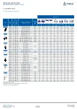
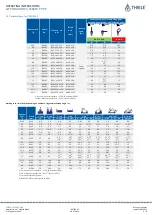
Take care to tighten the screws by the right torque shown in the table. As long as
it is ensured there is no load turning for a singular use and the lifting point cannot
be loosened a hand tightening of the lifting points by a suitable open -ended
spanner or ring spanner is sufficient. An additional check is necessary in case of a
repeated load lowering.
•
TWN 1830 and TWN 1884:
Take care not to exceed the tightening torque of 40 Nm for screws M10 and M12.
There must be made a chamfer on the hole for the thread:
Thread [mm]
Chamfer [mm]
M8
1,5
+0,5
x 45°
M10, M12
2,0
+0,5
x 45°
M16, M20
2,5
+0,5
x 45°
M24, M30
3,5
+0,5
x 45°
M36 - M48
4,0
+0,5
x 45°
M52
#
- M100
4,5
+0,5
x 45°
6
CONDITIONS OF USE
6.1
Normal Use
The top part of the lifting point including attachment link must always be freely
movable.
It must not rest on or be supported by other structural parts.
When attaching the components make sure the position of the lifting point alway s
enables forces to be exerted in longitudinal direction of the suspension link.
Make sure only the top parts of the lifting points turn into loading direction and not
the firmly secured stationary portion.
Using 4-leg chain link assemblies may cause higher risk because only 2 o pposite legs
carrying the load. Check the Working Load Limit of lifting point and chain link assembly
carefully and chose if necessary bigger sizes.
The force must be applied lengthwise to the suspension link.
TWN 1830:
The lifting point must not be used for a permanent or prolonged turning of the load.
to prefer
to avoid
not permitted
TWN 1890:
TWN 1884:
Components connected to the eyelet must always be able to move freely.
6.2
Use in through holes
#
If screwable lifting points are fastened by means of nuts in holes (e.g. of metal sheets),
the following conditions must be observed:
•
Rotating or turning the load is not permitted.
•
The strength class of the nuts must be 10 or higher.
•
The chamfer at the end of the screw thread must protrude from the nut.
•
It must be ensured that the component to be lifted is suitable to withstand the force
to be applied safely and without deformation, including the corresponding safety
factors.
•
Suitable action must be taken to ensure that the nut cannot loosen unintentionally,
e.g. suitable torque or threadlocker.


