background image


14  

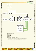
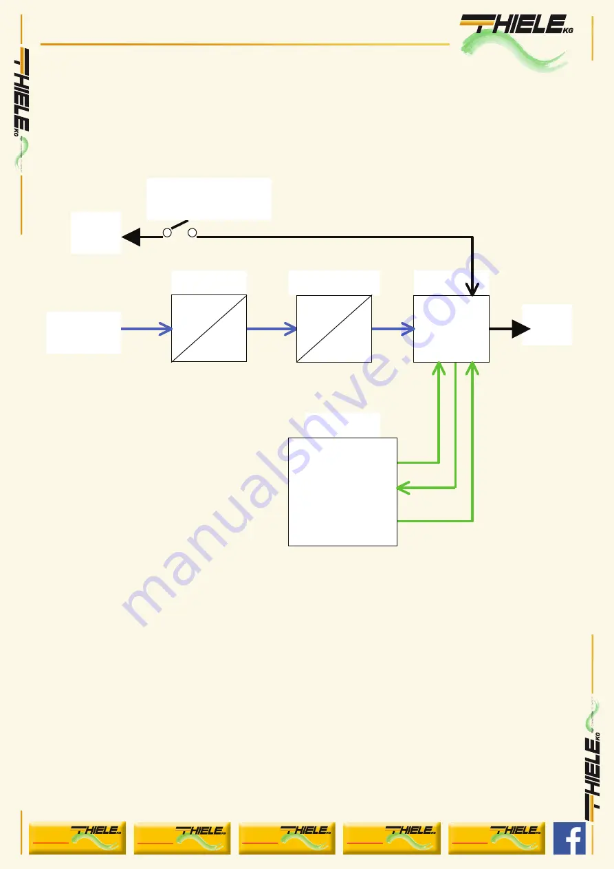
A: Inverter Fault   

B: Back Mode 

C: UPS Mode   

D: Inverter Mode


2-7-13 Flow Chart 


(A) AC INPUT SWITCH 

(B) DC TO DC   

(C) DC TO AC   

(D) SWITCH 

(E) UPS MODE & INVERTER MODE 


UPS MODE: If DC to AC Inverter fails the UPS mode takes over 

        INVERTER MODE: If UPS mode fails the Inverter takes over 


SWITCH 

(B) 

(C) 

DC           

AC 

DC           

DC 

UPS MODE 

INV MODE 

CONTROL 

(E) 

(D) 

DC Input 


(A)                 

AC   I/P 

Load 

City Power   

YOUR CONNECTION TO SAFETY

Thiele KG 

• V
orderer W

einberg 26 • D-71522 Backnang • T

el.: +49 (0)7191 3560-0 

• Fax.: +49 (0)7191 3560-19 

• info@thiele-kg.de 

• www

.thiele-kg.de

Thiele KG 

• V

orderer W

einberg 26 • D-71522 Backnang • T

el.: +49 (0)7191 3560-0 

• Fax.: +49 (0)7191 3560-19 

• info@thiele-kg.de 

• www

.thiele-kg.de

YOUR CONNECTION TO SAFETY

klick to

www

u-s-v

YOUR CONNECTION TO SAFETY

klick to

www

ACDC-DCDC

YOUR CONNECTION TO SAFETY

klick to

www

SYSTEME

YOUR CONNECTION TO SAFETY

klick to

www

CONTACT

YOUR CONNECTION TO SAFETY

klick to

www

CALLBACK

Summary of Contents for UIPSW-2U3KVA

Page 1: ...26 D 71522 Backnang Tel 49 0 7191 3560 0 Fax 49 0 7191 3560 19 info thiele kg de www thiele kg de Thiele KG Vorderer Weinberg 26 D 71522 Backnang Tel 49 0 7191 3560 0 Fax 49 0 7191 3560 19 info thiele kg de www thiele kg de YOUR CONNECTION TO SAFETY klick to www u s v YOUR CONNECTION TO SAFETY klick to www ACDC DCDC YOUR CONNECTION TO SAFETY klick to www SYSTEME YOUR CONNECTION TO SAFETY klick to ...

Page 2: ... General safety precautions 16 6 2 Precautions when working with batteries 17 7 Appendices A 7 1 Dip switch 17 7 2 Tune VR 17 YOUR CONNECTION TO SAFETY Thiele KG Vorderer Weinberg 26 D 71522 Backnang Tel 49 0 7191 3560 0 Fax 49 0 7191 3560 19 info thiele kg de www thiele kg de Thiele KG Vorderer Weinberg 26 D 71522 Backnang Tel 49 0 7191 3560 0 Fax 49 0 7191 3560 19 info thiele kg de www thiele kg...

Page 3: ...descent lights shavers sewing machines 1 1 4 Kitchen appliances microwave ovens refrigerators and freezers coffee makers blenders ice markers toasters 1 1 5 Industrial equipment metal halide lamp high pressure sodium lamp 1 1 6 Home entertainment electronics television VCRs video games stereos musical instruments satellite equipment YOUR CONNECTION TO SAFETY Thiele KG Vorderer Weinberg 26 D 71522 ...

Page 4: ... Input under voltage shut down 10 0VDC 20 0VDC 42 0VDC 90VDC 180VDC 10 0VDC 20 0VDC 42 0VDC 90VDC 180VDC Protection Overload Short Circuit Reverse Polarity Fuse Over Under Input Voltage Over Temperature Digital Display OVP UVP OTP OLP VAC AMP WATT VDC TEMP Hz Safety EN60950 1 EMC FCC Class A EN 55022 2006 Class A EN 61000 3 2 2006 EN 61000 3 3 1995 A1 2001 A2 2005 Interface Control Port RS 232 Wit...

Page 5: ...le kg de Thiele KG Vorderer Weinberg 26 D 71522 Backnang Tel 49 0 7191 3560 0 Fax 49 0 7191 3560 19 info thiele kg de www thiele kg de YOUR CONNECTION TO SAFETY klick to www u s v YOUR CONNECTION TO SAFETY klick to www ACDC DCDC YOUR CONNECTION TO SAFETY klick to www SYSTEME YOUR CONNECTION TO SAFETY klick to www CONTACT YOUR CONNECTION TO SAFETY klick to www CALLBACK ...

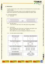
Page 6: ...ous status on the function screen Such as VAC Amp watts and so on When malfunction is occurred its display will be flashed on the screen 2 1 4 AC outlet Outlet sockets available YOUR CONNECTION TO SAFETY Thiele KG Vorderer Weinberg 26 D 71522 Backnang Tel 49 0 7191 3560 0 Fax 49 0 7191 3560 19 info thiele kg de www thiele kg de Thiele KG Vorderer Weinberg 26 D 71522 Backnang Tel 49 0 7191 3560 0 F...

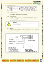
Page 7: ...g status WARNING Do not connect the 12V model to a 24V solar panel the unit will be destroyed immediately YOUR CONNECTION TO SAFETY Thiele KG Vorderer Weinberg 26 D 71522 Backnang Tel 49 0 7191 3560 0 Fax 49 0 7191 3560 19 info thiele kg de www thiele kg de Thiele KG Vorderer Weinberg 26 D 71522 Backnang Tel 49 0 7191 3560 0 Fax 49 0 7191 3560 19 info thiele kg de www thiele kg de YOUR CONNECTION ...

Page 8: ...NOT connected to any batteries and that all wiring is disconnected from any electrical sources Do not connect the output terminals of the inverter to an incoming AC source YOUR CONNECTION TO SAFETY Thiele KG Vorderer Weinberg 26 D 71522 Backnang Tel 49 0 7191 3560 0 Fax 49 0 7191 3560 19 info thiele kg de www thiele kg de Thiele KG Vorderer Weinberg 26 D 71522 Backnang Tel 49 0 7191 3560 0 Fax 49 ...

Page 9: ...mode or UPS mode freely If inverter mode fail the device will connect to UPS mode automatically If UPS mode fail the device will connect to Inverter mode automatically It will not influence the performance of server and could supply a uninterrupted power to the ultimate load 2 4 Quick hook up and testing 2 4 1 Unpack and inspect the power inverter check to see that the power switch in the OFF posi...

Page 10: ... all the DC connections are tight torque to 9 10 ft lbs 11 7 13Nm Loose connections will overheat and could result in a potential hazard CAUTION Reverse polarity connection will blow a fuse in Inverter and may permanently damage the inverter Damage caused by reverse polarity connection is not covered by our warranty WARNING You may observe a spark when you make this connection since current may fl...

Page 11: ...dure to connect the battery cables to the DC input terminals on the Inverter Your cables should be as short as possible ideally less than 10 feet 3 meters and large enough to handle the required Current in accordance with the electrical codes or regulations applicable to your installation Cables that are not an adequate gauge too narrow or are too long will cause decreased inverter performance suc...

Page 12: ...at the power inverter does not have to deliver the starting currents for all the loads at once 2 7 1 Controls and indicators The ON OFF switch turns the control circuit in the power inverter on and off Inverter operates from an input voltage ranging from 10 0 to 16 0 VDC for 12V models 20 0 to 320 0 VDC for 24V models 42 0 to 62 0 VDC for 48V models 90 to 140 VDC for 110V models 180 to 275VDC for ...

Page 13: ...C voltage value 2 7 6 Temperature Indictor LED displays light on TEMP as show as internal operating temperature value 2 7 7 Output Frequency DC Indictor LED displays light on Hz as show as output frequency value Please have the accuracy of 6 functions of display as below Function VAC AMP WATT VDC TEMP Frequency Range 100 120 VAC 200 240 VAC 0 30A 0 3KW 10 16 VDC 20 32 VDC 42 62 VDC 90 140 VDC 180 ...

Page 14: ...in a location which does not allow it to dissipate heat properly The power inverter will automatically back up once it has cooled off 2 7 11 Overload protection indicator OLP The overload indicator indicates that the power inverter has shut itself down When output voltage over continue power then must return to operate manually 2 7 12 Display Instructions A B C D YOUR CONNECTION TO SAFETY Thiele K...

Page 15: ... I P Load City Power YOUR CONNECTION TO SAFETY Thiele KG Vorderer Weinberg 26 D 71522 Backnang Tel 49 0 7191 3560 0 Fax 49 0 7191 3560 19 info thiele kg de www thiele kg de Thiele KG Vorderer Weinberg 26 D 71522 Backnang Tel 49 0 7191 3560 0 Fax 49 0 7191 3560 19 info thiele kg de www thiele kg de YOUR CONNECTION TO SAFETY klick to www u s v YOUR CONNECTION TO SAFETY klick to www ACDC DCDC YOUR CO...

Page 16: ...ding voltmeter Use true RMS reading meter and cable Ref point 2 4 7 Load Display OLP flash Over load Reduce load No output voltage Fault input voltage Low High input voltage Recharge battery check connections and cable Ref point 2 7 1 No output voltage Over Temp indicator Load less than 1500W Thermal shutdown Improve ventilation Make sure ventilation openings in inverter are not obstructed Reduce ...

Page 17: ...r or obstruct the ventilation openings Do not install the Inverter in a zero clearance compartment Overheating may result 6 1 2 To avoid a risk of fire and electronic shock Make sure that existing wiring is in good electrical condition and that wire size is not undersized Do not operate the Inverter with damaged or substandard wiring 6 1 3 This equipment contains components which can produce arcs ...

Page 18: ...tal causing a severe burn 7 Appendices A 7 1 Dip Switch at the left side of inverter S1 Freq Hz S2 S3 Baud Rate When you set up S1 S3 please reset the inverter and let update data through CPU 7 2 Tune VR Tune VR VAC output voltage from 100 120 VAC or 200 240 VAC The VAC value will gradually increase tune VR from right to left RE MARK The user manual is subject to change without notice YOUR CONNECT...

Reviews: