background image

STORMBEE Software User Manual 


Think 3D BVBA


Version N°1.1, last modified 30/09/2018 

23 


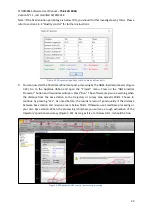
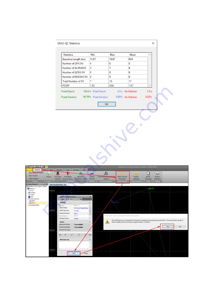
Note: if the fixed solution percentage is below 70%, you should further investigate why this is. Please 
refer to section 3.3.4 

Quality control

 for further instructions.


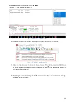
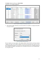
Figure 3.21 Applanix single base station data quality analysis 

9.


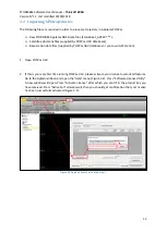
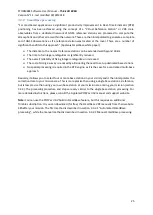
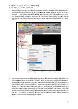
You can now start the final data refinement post-processing by the GNSS-inertial processor (Figure 
3.22). 

Go  to  the  Applanix  ribbon  and  open  the  “Project”  menu.  Press  on  the  “GNSS

-Inertial 

Processor” button an

its window will open. Press “Run”. 

The software may issue a warning when 

the  distance  from  the  base  station  to  the  trajectory  or  survey  area  exceeds  20km.  Choose  to 
continue 

by pressing “Yes”

. As noted before,  the  results  remain of good quality if the  distance 

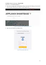
between base station and mission area is below 50km. Otherwise use SmartBase processing or 
your own base station. When the processing is finished, you will see a rough estimation of the 

trajectory’s positional accuracy (

Figure 3.23). As long as it is at or below 0.1m, it should be fine. 


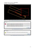
Figure 3.22 Applanix GNSS-inertial processor processing 

Summary of Contents for STORMBEE

Page 1: ...STORMBEE Software User Manual Think 3D BVBA 30 09 2018...

Page 2: ...STORMBEE Software User Manual Think 3D BVBA Version N 1 1 last modified 30 09 2018 ii PAGE INTENTIONALLY LEFT BLANK...

Page 3: ...Manual Think 3D BVBA Version N 1 1 last modified 30 09 2018 iii Version control Author Date Version Comments Adaptations Jon Verbeke 26 04 2018 1 0 Initial version Jon Verbeke 30 09 2018 1 1 Updated t...

Page 4: ...STORMBEE Software User Manual Think 3D BVBA Version N 1 1 last modified 30 09 2018 iv PAGE INTENTIONALLY LEFT BLANK...

Page 5: ...le 5 3 Applanix POSPac UAV 11 3 1 Installation POSPac UAV 11 3 2 Importing GPS trajectories 12 3 3 Processing raw GNSS data to refined GNSS data 17 3 3 1 Single base processing 18 3 3 2 SmartBase proc...

Page 6: ...BA Version N 1 1 last modified 30 09 2018 vi 5 2 Visualisation postprocessed point cloud 57 5 2 1 Import data files 57 5 2 2 Verify accuracy results 59 5 3 Examples post processed data 68 6 STORMBEE a...

Page 7: ...3 6 Applanix GNSS data import progress window 1 14 Figure 3 7 Applanix GNSS data import progress window 2 15 Figure 3 8 Applanix GNSS antenna used 15 Figure 3 9 Applanix trajectory with zoomed view o...

Page 8: ...cycle slips 41 Figure 3 49 Applanix export LIDAR event data for BEEFLEX processing 42 Figure 3 50 Applanix export trajectory data for BEEFLEX processing step 1 43 Figure 3 51 Applanix export trajecto...

Page 9: ...re cross section properties window 63 Figure 5 12 CloudCompare point cloud with cross section properties window and interactors 63 Figure 5 13 CloudCompare point cloud cross section narrow slice 64 Fi...

Page 10: ...STORMBEE Software User Manual Think 3D BVBA Version N 1 1 last modified 30 09 2018 x PAGE INTENTIONALLY LEFT BLANK...

Page 11: ...STORMBEE Software User Manual Think 3D BVBA Version N 1 1 last modified 30 09 2018 xi List of tables N A...

Page 12: ...STORMBEE Software User Manual Think 3D BVBA Version N 1 1 last modified 30 09 2018 xii PAGE INTENTIONALLY LEFT BLANK...

Page 13: ...ser Manual Think 3D BVBA Version N 1 1 last modified 30 09 2018 xiii Symbols and abbreviations GNSS Global Navigation Satellite System GPS Global Positioning System IMU Inertial Measurement Unit RAM R...

Page 14: ...STORMBEE Software User Manual Think 3D BVBA Version N 1 1 last modified 30 09 2018 xiv PAGE INTENTIONALLY LEFT BLANK...

Page 15: ...ckage FARO Scene Processor Quad core X64 Intel Core i7 Xeon 8 physical cores Graphics Card Dedicated graphics card OpenGL 4 1 or higher at least 4 GB Memory o For Stereo Rendering NVIDIA Quadro o For...

Page 16: ...STORMBEE Software User Manual Think 3D BVBA Version N 1 1 last modified 30 09 2018 2 Figure 1 1 STORMBEE post processing software workflow...

Page 17: ...ata from FARO scanner and GNSS module 2 1 Extracting data from FARO scanner 2 1 1 Extraction 1 Ensure that the FARO scanner is powered off 2 Remove the SD card of the FARO scanner Please refer to the...

Page 18: ...h your laptop Copy the data to your laptop in a folder of your choice Figure 2 2 Insert SD card into computer 2 1 2 Format The FARO scanner data is stored within a folder named fls It should contain s...

Page 19: ...trieval uses FileZilla Client Basic or equivalent software Please download and install program from https filezilla project org 1 Connect battery 1 is sufficient Figure 2 4 Data extraction connect bat...

Page 20: ...e the adapters usually Bluetooth Ethernet and Wi Fi Right click on Properties Select Internet Protocol version 4 TCP IPv4 and click below on Properties You should now see the IP and DNS properties win...

Page 21: ...STORMBEE Software User Manual Think 3D BVBA Version N 1 1 last modified 30 09 2018 7 Figure 2 7 Ethernet settings 2 Figure 2 8 Ethernet settings 3...

Page 22: ...an skip this step For first use you need to add the STORMBEE as a new site If you have set this before skip to step 7 Press New Site change its name to STORMBEE by simply clicking on the text and fill...

Page 23: ...hand window Figure 2 11 FileZilla connect to STORMBEE 9 Find the data file with the newest date of creation Last modified corresponding to your flight Select all relevant files In the left hand windo...

Page 24: ...ansfer successful Figure 2 14 FileZilla file transfer succesful 11 Close FileZilla disconnect the ethernet cable and power off the GNSS avionics and FARO Focus scanner by pressing the large button wit...

Page 25: ...eed to freely register with Trimble to see the map of all base stations worldwide Figure 3 1 In case no base stations are near your mission location POSPac UAV allows you to use Applanix SmartBase opt...

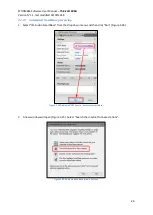
Page 26: ...ed by POSPac UAV databases or your own GPS station 1 Open POSPac UAV 2 If this is your very first time running POSPac UAV please activate your license to unlock all features Go to the Applanix ribbon...

Page 27: ...13 Figure 3 3 Applanix license activation step 2 3 In POSPac ribbon at the top select Project New Default Project Figure 3 4 Figure 3 4 Applanix new default project 4 Choose File Save project As Speci...

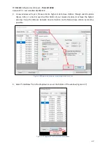
Page 28: ...he box to open the file explorer and finally select Import Figure 3 5 Importing GNSS data files from PosPac ribbon 6 The files will begin to import into the project A progress bar will appear Once the...

Page 29: ...4 Figure 3 8 Applanix GNSS antenna used The raw trajectory will now appear in the working window Ensure that the event icons orange triangles are present on the trajectory Figure 3 9 These event times...

Page 30: ...3D BVBA Version N 1 1 last modified 30 09 2018 16 Figure 3 9 Applanix trajectory with zoomed view of orange event triangles Figure 3 10 Applanix import failure error message Figure 3 11 Applanix IMU...

Page 31: ...s of that time period to be used to estimate an initial heading Figure 3 12 The default should be set to Initialize from GNSS track heading Figure 3 12 Applanix processing initialisation settings Once...

Page 32: ...f the distance in between is higher than 50km using SmartBase requires subscription or own local base station might be a better choice depending on your accuracy needs 1 Select IN Fusion Single Base f...

Page 33: ...ase station as small as possible Figure 3 16 Applanix data base import high rate data sites 4 Select Single Base from the dropdown menu at the bottom of the window Figure 3 17 Note Make sure your coun...

Page 34: ...oad and import a base station it gives a status error File not found This might be due to maintenance of that station at the time of the mission or that the base station data was not published that pe...

Page 35: ...tions import list 6 Once Close has been selected the main window will have zoomed out and show your base station s location with respect to your mission trajectory Figure 3 19 Simply zoom into your mi...

Page 36: ...set single base station 8 Applanix will automatically perform a quality control analysis of the data of your flight trajectory and base station data and show you a report Figure 3 21 There are three t...

Page 37: ...the Project menu Press on the GNSS Inertial Processor button and its window will open Press Run The software may issue a warning when the distance from the base station to the trajectory or survey are...

Page 38: ...Software User Manual Think 3D BVBA Version N 1 1 last modified 30 09 2018 24 Figure 3 23 Applanix GNSS Inertial processing completed 10 Please go to sections 3 3 4 and 3 3 5 for quality control and da...

Page 39: ...of doing a survey is reduced by eliminating the need to set up dedicated base stations No special processing is required in the RTK engine as it is the case for a centralized multi base approach Basic...

Page 40: ...utomated SmartBase processing 1 Select IN Fusion SmartBase from the dropdown menu and then click Run Figure 3 24 Figure 3 24 Applanix GNSS Inertial processor SmartBase 2 A new window will open Figure...

Page 41: ...igure 3 26 It is best to search within 50km of your mission location to achieve the highest accuracy Keep the distance between mission location and reference base station as small as possible Figure 3...

Page 42: ...possible that when trying to download and import a base station it gives a status error File not found This might be due to maintenance of that station at the time of the mission or that the base sta...

Page 43: ...ontrol station 8 You can start the final data refinement processing by the GNSS inertial processor Figure 3 30 Go to the Applanix ribbon and open the Project menu Press on the GNSS Inertial Processor...

Page 44: ...ssor processing SmartBase 3 3 2 2 Manual SmartBase processing This is the free option but you have to register yourself Please note that the GNSS correction data of a VRS close by your mission locatio...

Page 45: ...ou have not registered a Trimble account click on Try it Free and create your own account Once you have an account you can click on Log In Figure 3 32 Figure 3 32 Applanix SmartBase Login and register...

Page 46: ...3D BVBA Version N 1 1 last modified 30 09 2018 32 4 Search you mission location in the upper right box Figure 3 34 and Figure 3 35 Figure 3 34 Applanix SmartBase search mission location Figure 3 35 A...

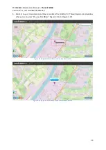
Page 47: ...8 33 5 Zoom in on your mission area and draw a marker in the middle of it This will open a small window where you can press Preview SmartBase Figure 3 36 and Figure 3 37 Figure 3 36 Applanix SmartBase...

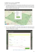
Page 48: ...e quality of the VRS data ranging from fail very bad to Excellent very good Press the Request SmartBase button to request the VRS data Figure 3 38 Figure 3 38 Applanix SmartBase VRS info 7 Fill in you...

Page 49: ...ase station has been placed specifically for the survey or the desired base station has been sourced from a database not listed in the POSPac software you will need to import the base station data in...

Page 50: ...ts to show individual quality control figures To generate a PDF report open the Reports ribbon and click on QC Report Figure 3 42 A new window will open in which you can choose the directory where you...

Page 51: ...number of possible graphs to view This manual focuses on the most important ones that will ensure overall accuracy These are described in sections 4 3 4 2 to 4 3 4 6 When viewing the graphs select the...

Page 52: ...hint at an error Expand Smoothed Performance Metrics Reference Frame and inspect North Position Error RMS m East Position Error RMS m and Down Position Error RMS m Figure 3 44 Figure 3 44 Applanix qu...

Page 53: ...planix raw trajectory log file An example of these lever arm errors is shown in Figure 3 46 3 3 4 5 Position Dilution of Precision PDOP Quality check optional PDOP describes error caused by the relati...

Page 54: ...STORMBEE Software User Manual Think 3D BVBA Version N 1 1 last modified 30 09 2018 40 Figure 3 46 Applanix quality lever arm settings Figure 3 47 Applanix quality control display plot PDOP...

Page 55: ...illustration of how consistent the calculated trajectory will be It is common for GLONASS satellites to show a higher number of cycle slips and so special attention should be shown to the GPS satellit...

Page 56: ...saved 3 3 5 1 LiDAR Event Data The LiDAR event data is automatically exported from POSPac when the GPS observation files are added into the software To locate this file using windows explorer open the...

Page 57: ...will open where you can specify the directory in which to save the trajectory data Leave as default Choose the ASCII Export File Format and press Export Figure 3 50 Applanix export trajectory data fo...

Page 58: ...f the trajectory appears to be importing correctly and then stops likely the first file is fine but the last has an error However if the trajectory does not begin importing at all likely the first fil...

Page 59: ...ectory for the presence of any errors Figure 3 55 Verify both POS Data Import and IMU Data Continuity Checking have no errors present Figure 3 55 Applanix opening message logs dropdown menu Scroll to...

Page 60: ...ing For this example the time tag Figure 3 57 291178 568 seconds occurs before the Start Time of the IMU scan Figure 3 58 291178 573 seconds so it has no influence on the scan data quality as the erro...

Page 61: ...the software automatically excludes all satellites below a 10 degree elevation above the horizon This setting can be changed in an attempt to force the software to use satellites that were observed ju...

Page 62: ...STORMBEE Software User Manual Think 3D BVBA Version N 1 1 last modified 30 09 2018 48 PAGE INTENTIONALLY LEFT BLANK...

Page 63: ...ingle file or flexibly extract selected flight strips through an intuitive user interface based on a Google Maps background BEEFLEX is designed with user friendliness in mind allowing anyone to start...

Page 64: ...pe of purchase the key will be valid for a limited or unlimited period The number of days until the license becomes expired is shown on the bottom of the BEEFLEX program window To enter a new license...

Page 65: ...l files required by BEEFLEX 2 Select the folder in which all relevant files are stored Figure 4 5 Do not enter the folder only select the folder itself Figure 4 5 BEEFLEX select folder flight and scan...

Page 66: ...rajectory on a Google Maps like background You can also select the satellite view which shows the terrain Figure 4 8 In addition BEEFLEX shows the height profile of the drone during the flight at the...

Page 67: ...of the flight and corresponding scan data which you want to use When hovering with your mouse above the flight data height profile a small green dot will simultaneously show the synchronised location...

Page 68: ...oured green blue Figure 4 10 You can select multiple portions of the flight by simply repeating this clicking and dragging procedure Figure 4 11 The selected sections are listed in listed in the left...

Page 69: ...ROCEED BEEFLEX will first export the relevant point cloud data in E57 format Figure 4 13 after which if the LAS box was checked the LAS format files will be generated and exported Figure 4 14 For both...

Page 70: ...Think 3D BVBA Version N 1 1 last modified 30 09 2018 56 Figure 4 13 BEEFLEX data processing progress E57 format Figure 4 14 BEEFLEX data processing progress LAS format Figure 4 15 BEEFLEX refined poin...
Page 71: ...to use fls files It is best to first install CloudCompare before installing Scene Full Version 30 day trial software package Installing CloudCompare after you installed the Scene Full Version 30 day...

Page 72: ...ORMBEE Software User Manual Think 3D BVBA Version N 1 1 last modified 30 09 2018 58 Figure 5 1 CloudCompare import files through desktop icon Figure 5 2 CloudCompare import point cloud properties wind...

Page 73: ...s much as possible The best method of doing so is by assigning different colours to each flight segment and afterwards analysing manually how well they overlap For better visualisation the example sca...

Page 74: ...that segment by going to Edit Colors Set Unique A window will open that will allow you to select a colour Figure 5 6 Repeat this for each flight segment Tip Pick colours with lots of contrast with re...

Page 75: ...the top folders but the individual point clouds with the small cloud symbol next to it Figure 5 8 Keep pressing the Ctrl button while left clicking on each point cloud to select more than one point cl...

Page 76: ...D BVBA Version N 1 1 last modified 30 09 2018 62 Figure 5 9 CloudCompare all point clouds selected in navigation menu 4 Go to Tools Segmentation and left click Cross Section Figure 5 10 Figure 5 10 Cl...

Page 77: ...properties Figure 5 11 but also arrows interactors will appear that can be dragged press and hold mouse left button on arrow or rotated press and hold mouse left button on circle donut around arrow Fi...

Page 78: ...ompare point cloud cross section narrow slice 7 Zoom in on a piece of the point cloud slice where multiple coloured points representing different flight segments are present Figure 5 14 Zoom in until...

Page 79: ...eference distance in the right bottom corner For this cross section you can see that the synchronisation of the different data sets has around 10cm accuracy This does NOT mean that the point cloud dat...

Page 80: ...ree or more different coloured segments you save time so if possible choose these kinds of cross sections Other examples of the same point cloud data set are shown in Figure 5 17 Figure 5 18 and Figur...

Page 81: ...ftware User Manual Think 3D BVBA Version N 1 1 last modified 30 09 2018 67 Figure 5 18 CloudCompare point cloud slice zoomed in example 2 Figure 5 19 CloudCompare cross section in plane quality contro...

Page 82: ...ost processed data The final point cloud Figure 5 20 can then be used to generate 2D and 3D drawings and models of the inspected object with 3rd party software Figure 5 21 and Figure 5 22 Figure 5 20...

Page 83: ...STORMBEE Software User Manual Think 3D BVBA Version N 1 1 last modified 30 09 2018 69 Figure 5 22 2D drawing based on final post processed point cloud data...

Page 84: ...STORMBEE Software User Manual Think 3D BVBA Version N 1 1 last modified 30 09 2018 70 PAGE INTENTIONALLY LEFT BLANK...

Page 85: ...section Figure 6 1 STORMBEE hastag calibration flight path example STORMBEE operators should send through a calibration suitable set of scan and GNSS data to Think3D every 6 months or 20 hours of fli...

Page 86: ...values with the correct laser scan data set Follow the next steps to modify the calibration values 1 Go to the folder where the files are stored that are required to do the final processing in BEEFLE...

Page 87: ...tions Figure 6 4 FARO scanner calibration parameters heading pitch and roll 4 Replace the heading pitch and roll values with the new values provided by Think3D for your specific STORMBEE 5 Save the ch...

Page 88: ...STORMBEE Software User Manual Think 3D BVBA Version N 1 1 last modified 30 09 2018 74 PAGE INTENTIONALLY LEFT BLANK...

Reviews: