MAN-000018
10
REVISION A
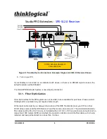
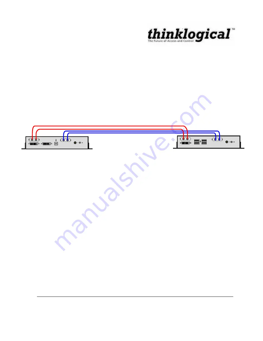
Connect your fiber cable to the ST-type connector on each SPE pair (one Transmitter and one
Receiver). Dress the cable so it will not get crushed, pinched or otherwise damaged.
When connecting the fiber optic cables, you must be sure to:
Connect the fiber connector labeled ‘L1 (T)’ on the Transmitter to the fiber connector
labeled ‘L1 (R)’ on the Receiver.
Connect the fiber connector labeled ‘L2 (T)’ on the Transmitter to the fiber connector
labeled ‘L2 (R)’ on the Receiver.
Connect the fiber connector labeled ‘L3’ on the Transmitter to the fiber connector
labeled ‘L3’ on the Receiver.
Connect the fiber connector labeled ‘L4’ on the Transmitter to the fiber connector
labeled ‘L4’ on the Receiver.
Figure 6: Proper Connection of Fiber Cable Shown
*Note:
When you connect the fibers,
THE FIBER CABLE SHOULD NOT BE CROSSED
.
3.3.2. Digital Video (DVI-D) Input – Transmitter
The SPE Transmitter unit connects to your DVI video source (DVI-D video card) using the provided DVI-
D male-to-male cable (CBL000013-002MR). The Digital Video Input connector on the transmitter will
NOT accept other form factors of DVI connectors (DVI-I or DVI-A).
3.3.3. Digital Video (DVI-D) Output - Receiver
The SPE Receiver unit connects to your DVI video monitor, projector, or other viewing device. Your
device must have a DVI-D connector on its cable.
5VDC
L 3
L4
L1
T
L2
R
USB1 .1
DVI LOCAL DISPLAY
DUAL LINK
DVI FROM CPU
DUAL LINK
POWER
5VDC
L 3
L4
L1
R
L2
T
POWER
USB 1.1
DVI TO DISPLAY
DUAL LINK
SPE-DL1.1
transmitter
SPE-DL1.1
receiver
Summary of Contents for DCS StudioPRO
Page 2: ......
Page 6: ......
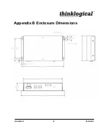
Page 28: ...MAN 000018 22 REVISION A Appendix B Enclosure Dimensions...


