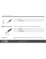
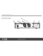
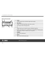
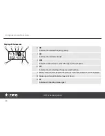

8 DC INPUT
Connect the cable of the supplied mains adapter to this socket. If using another power adapter make sure it provides
the correct voltage, plug polarity and sufficient power.
9, 10 LEFT INPUT / RIGHT INPUT
XLR/1/4" combo sockets (left and right channel) for the direct connection to a mixing console or another audio
device that is used as signal source.
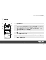
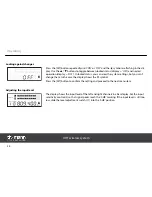
11 PAD
Level adjustment switch. Set this switch to the ‘–12 dB’ position to attenuate the input signals by 12 dB. In ‘0 dB‘ posi‐
tion, there is no attenuation.
Beneath, you find the indication of the frequency range, in which the unit operates. The specification here must
match the specification on the rear side of the receiver.
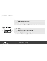
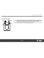
12 ANTENNA
BNC mounting socket for the supplied UHF antenna. Make sure the frequency indicated on the antenna matches the
frequency range indicated on the transmitter.
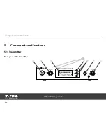
Components and functions
IEM 100
25
Summary of Contents for IEM 100
Page 1: ...IEM 100 UHF wireless system user manual...
Page 56: ...Notes UHF wireless system 56...
Page 57: ...Notes IEM 100 57...
Page 58: ...Notes UHF wireless system 58...
Page 59: ......
Page 60: ...Musikhaus Thomann e K Treppendorf 30 96138 Burgebrach Germany www thomann de...