background image

1.

Press 

[ENTER]

 and then 

[UP]

 or 

[DOWN]

 repeatedly until the display shows 

‘Settings’

.

Confirm with 

[ENTER]

.

2.

Press 

[UP]

 or 

[DOWN]

 repeatedly until the display shows 

‘Auto Lock’

. Confirm with

[ENTER]

.

3.

Use 

[UP]

 or 

[DOWN]

 to choose between 

‘On’

 (keylock on) and 

‘Off’

 (keylock off).

4.

Press 

[ENTER]

 to accept the selection.

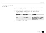
1.

Press 

[ENTER]

 and then 

[UP]

 or 

[DOWN]

 repeatedly until the display shows 

‘Settings’

.

Confirm with 

[ENTER]

.

2.

Press 

[UP]

 or 

[DOWN]

 repeatedly until the display shows 

‘IR Remote’

. Confirm with

[ENTER]

.

3.

Use 

[UP]

 or 

[DOWN]

 to choose between 

‘On’

 (RC enabled) and 

‘Off’

 (RC disabled).

4.

Press 

[ENTER]

 to accept the selection.

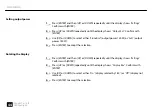
Enabling keylock

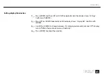
Enabling IR remote control (RC)

receiver

Operating


50

2bright Par 18 IP

LED spotlight

Summary of Contents for Ignition 2bright Par 18 IP

Page 1: ...2bright Par 18 IP LED spotlight User manual...

Page 2: ...Musikhaus Thomann Thomann GmbH Hans Thomann Stra e 1 96138 Burgebrach Germany Telephone 49 0 9546 9223 0 E mail info thomann de Internet www thomann de 22 04 2020 ID 481058...

Page 3: ...2 Safety instructions 11 3 Features 16 4 Installation 18 5 Starting up 22 6 Connections and controls 26 7 Operating 32 7 1 Starting the device 32 7 2 Operating on the unit 32 7 3 Menu overview 53 7 4...

Page 4: ...in 9 channel DMX mode 60 7 8 Functions in 11 channel DMX mode 65 8 Technical specifications 71 9 Plug and connection assignments 74 10 Troubleshooting 75 11 Cleaning 77 12 Protecting the environment 7...

Page 5: ...ilable to all persons using this device If you sell the device to another user be sure that they also receive this manual Our products and user manuals are subject to a process of continuous developme...

Page 6: ...se the search function in the electronic version to find the topics of interest for you quickly Online guides Our online guides provide detailed information on technical basics and terms Personal cons...

Page 7: ...terings for connectors and controls are marked by square brackets and italics Examples VOLUME control Mono button Texts and values displayed on the device are marked by quotation marks and italics Exa...

Page 8: ...an arrow Example 1 Switch on the device 2 Press Auto Automatic operation is started 3 Switch off the device 1 3 Symbols and signal words In this section you will find an overview of the meaning of sym...

Page 9: ...and signal word indicates a pos sible dangerous situation that can result in death or serious injury if it is not avoided NOTICE This combination of symbol and signal word indicates a pos sible dange...

Page 10: ...Warning signs Type of danger Warning dangerous optical radiation Warning suspended load Warning danger zone General information 10 2bright Par 18 IP LED spotlight...

Page 11: ...erty damage No liability will be assumed for damages resulting from improper use This device may be used only by persons with sufficient physical sensorial and intellectual abilities and having corres...

Page 12: ...ike from the unit They could swallow the pieces and choke Never let children unattended use electrical devices DANGER Electric shock caused by short circuit Always use proper ready made insulated main...

Page 13: ...e present Never remove any covers There are no user serviceable parts inside Do not use the device if covers protectors or optical components are missing or damaged WARNING Eye damage caused by high l...

Page 14: ...The surface of the device can become very hot during operation Do not touch the device with bare hands during operation and after switching off wait for at least 15 minutes NOTICE Risk of fire Do not...

Page 15: ...e AC outlet is protected by a residual current circuit breaker Failure to do so could result in damage to the device and possibly injure the user Unplug the device before electrical storms occur and w...

Page 16: ...n 8 storable user colours n Master Slave operation n Protection class IP65 Equipment with protection class IP65 are dust tight and completely protected against contact first code number They are also...

Page 17: ...nt must be checked regularly to ensure a fault free operation In cases of doubt consult a specialist workshop in due time For technological reasons the light output of LEDs decreases over their lifeti...

Page 18: ...n or storage use the original packaging or your own packaging material suitable for transport or storage respectively WARNING Risk of injury caused by falling objects Make sure that the installation c...

Page 19: ...in the chapter Tech nical Specifications of the User Manual NOTICE Use of stands When mounting the device onto a stand ensure that the stand is in a safe and stable position and that the weight of the...

Page 20: ...onnect the DMX input or output to audio devices such as mixers or ampli fiers NOTICE Possible damage due to moisture Moisture entering into open connectors plugs and couplers of DMX or power cords can...

Page 21: ...d truss Use the openings of the bracket provided for mounting Always work from a stable platform whenever installing moving or servicing the unit In doing so the area underneath the unit must be cordo...

Page 22: ...te all connections while the device is off Use the shortest possible high quality cables for all connections Take care when running the cables to prevent tripping hazards Starting up 22 2bright Par 18...

Page 23: ...evice Connect the output of the first DMX device to the input of the second one and so on to form a daisy chain Always ensure that the output of the last DMX device in the daisy chain is terminated wi...

Page 24: ...d show This function is ideal when you want to start a show immediately Connect the DMX output of the master device to the DMX input of the first slave device Then connect the DMX output of the first...

Page 25: ...nts to the housing base of the remote control Slide the battery holder back into the remote until it clicks into place When shipping the battery is already installed in the remote and protected agains...

Page 26: ...6 Connections and controls Connections and controls 26 2bright Par 18 IP LED spotlight...

Page 27: ...ed as 3 pin XLR panel socket IP65 5 DMX IN DMX input designed as 3 pin XLR panel plug IP65 6 Display and keypad MENU Activates the main menu toggles between the menu levels or closes a submenu DOWN De...

Page 28: ...Power cord with Power Twist TR1 cable connector for the power supply of the device 8 POWER OUT Power cord with Power Twist TR1 cable connector for powering further devices 9 Safety cable eyelet Connec...

Page 29: ...12 Changes the auto or fade programmes increases or decreases the strobe speed 13 Selection of a mixed colour Remote control Connections and controls 2bright Par 18 IP 29 LED spotlight...

Page 30: ...s the Strobe effect flash on or off Fullon Turns all colours to full brightness Auto Starts a preprogrammed automatic show Fade Turns the Fade effect colour transition on or off 15 Buttons to select a...

Page 31: ...The IR remote control only works if the receiver on the device is activated via the menu Connections and controls 2bright Par 18 IP 31 LED spotlight...

Page 32: ...ess ENTER to activate the main menu 2 Press again UP or DOWN to call up further menu items 3 To activate the respectively shown menu item press ENTER 4 Press UP or DOWN to change the respectively indi...

Page 33: ...All set values are retained even when you switch the device off and disconnect it from the mains Operating 2bright Par 18 IP 33 LED spotlight...

Page 34: ...ection This setting is only relevant when the device is controlled via DMX Make sure that this number matches the configuration of your DMX controller The following table shows the highest pos sible D...

Page 35: ...DMX Channel Confirm with ENTER 2 Use UP or DOWN to select the desired DMX mode 2 3 6 9 or 11 channels Depending on the selected mode the display shows 2CH 3CH 6CH 9CH or 11CH 3 Press ENTER to accept...

Page 36: ...Confirm the selection with ENTER 3 Use UP or DOWN to select the desired automatic programme display shows Program 1 Program 16 Confirm with ENTER 4 Press UP or DOWN to select the desired submenu or th...

Page 37: ...ith ENTER 2 Press UP or DOWN repeatedly until the display shows Sound Confirm with ENTER 3 Press UP or DOWN to select the desired value for the microphone sensitivity display shows 000 100 4 Press ENT...

Page 38: ...with ENTER 3 Use UP or DOWN to select one of the 35 colour macros display shows Color1 Color35 or turn off the colour display shows Color Off Confirm with ENTER 4 Press UP or DOWN to select the desir...

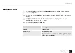
Page 39: ...you can to adjust individually 4 Press ENTER repeatedly to activate the desired sub menu 5 To set the intensity of the dimmer the frequency of the strobe effect or the intensity of the colour use UP...

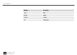
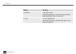
Page 40: ...Display Meaning Blue Blue White White Amber Amber UV Ultraviolet Operating 40 2bright Par 18 IP LED spotlight...

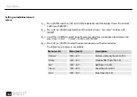
Page 41: ...DOWN to select the desired submenu or the desired value The following sub menus are available Menu level 3 Menu level 4 Description Dimmer 000 255 Dimmer intensity CTC 2800K 8000K Colour temperature 2...

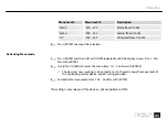
Page 42: ...ur dis play shows Color1 Color8 Confirm with ENTER 4 Press UP or DOWN to select the desired submenu or the desired value The following sub menus are available Menu level 4 Menu level 5 Description Dim...

Page 43: ...e display shows Slave Con firm with ENTER 2 Use UP or DOWN to select the menu item Yes Confirm with ENTER The device is now working in slave mode i e it will exactly copy the movement of the controlli...

Page 44: ...output power 180 W 4 Press ENTER to accept the selection 1 Press ENTER and then UP or DOWN repeatedly until the display shows Settings Confirm with ENTER 2 Press UP or DOWN repeatedly until the displa...

Page 45: ...DOWN repeatedly until the display shows Display Bkl Confirm with ENTER 3 Use UP or DOWN to choose between On display permanently on and Off display turns off after a few seconds in case of inactivity...

Page 46: ...Use UP or DOWN to choose between Hold Blackout and Emergency Light to make the setting to be used when the DMX controller fails 4 Press ENTER to accept the selection Display Meaning Hold Last DMX val...

Page 47: ...ith ENTER 3 Use UP or DOWN to select the desired dimmer curve display shows Linear Exponential Logarithmic or S Curve 4 Press ENTER to accept the selection Display Meaning Linear Linear course Exponen...

Page 48: ...rse Inverted quadratic curve with a steep course at the beginning and a flat course at the end S Curve S curve shaped course Non linear curve with a distinctive flat course at the beginning and end Op...

Page 49: ...onfirm with ENTER 3 Use UP or DOWN to select the desired response behaviour of the dimmer display shows LED or Halogen 4 Press ENTER to accept the selection Display Meaning LED The dimmer setting for...

Page 50: ...keylock off 4 Press ENTER to accept the selection 1 Press ENTER and then UP or DOWN repeatedly until the display shows Settings Confirm with ENTER 2 Press UP or DOWN repeatedly until the display shows...

Page 51: ...y shows the message Reset Now 3 Confirm with ENTER to start the reset 1 Press ENTER and then UP or DOWN repeatedly until the display shows System Info Confirm with ENTER 2 Press UP or DOWN until the d...

Page 52: ...display shows System Info Confirm with ENTER 2 Press UP or DOWN until the display shows Operation Hours Confirm the selection with ENTER The operation hours of the device are displayed Operating hour...

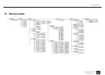
Page 53: ...7 3 Menu overview Operating 2bright Par 18 IP 53 LED spotlight...

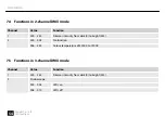
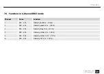
Page 54: ...ark 0 to bright 255 2 000 005 No function 006 255 Colour temperature of 3200 K to 7200 K 7 5 Functions in 3 channel DMX mode Channel Value Function 1 000 255 Dimmer intensity from dark 0 to bright 255...

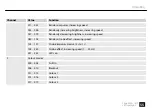
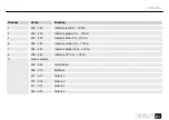
Page 55: ...decreasing brightness increasing speed 080 102 Random strobe effect increasing speed 103 127 Strobe impulses interval 5 s to 1 s 128 250 Strobe effect increasing speed 1 20 Hz 251 255 LEDs on 3 Colour...

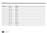
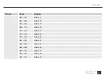
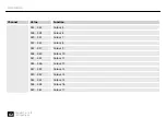
Page 56: ...Colour 5 026 028 Colour 6 029 031 Colour 7 032 034 Colour 8 035 037 Colour 9 038 040 Colour 10 041 043 Colour 11 044 046 Colour 12 047 049 Colour 13 050 052 Colour 14 053 055 Colour 15 056 058 Colour...

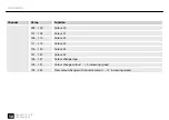
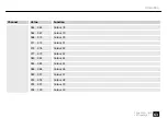
Page 57: ...lour 18 065 067 Colour 19 068 070 Colour 20 071 073 Colour 21 074 076 Colour 22 077 079 Colour 23 080 082 Colour 24 083 085 Colour 25 086 088 Colour 26 089 091 Colour 27 092 094 Colour 28 095 097 Colo...

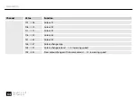
Page 58: ...110 Colour 32 111 115 Colour 33 116 120 Colour 34 121 125 Colour 35 126 127 Colour change stop 128 191 Colour change colour 1 12 increasing speed 192 255 Slow colour change with dissolve colour 1 12...

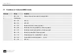
Page 59: ...alue Function 1 000 255 Intensity red 0 100 2 000 255 Intensity green 0 100 3 000 255 Intensity blue 0 100 4 000 255 Intensity white 0 100 5 000 255 Intensity amber 0 100 6 000 255 Intensity UV 0 100...

Page 60: ...011 033 Random impulses increasing speed 034 056 Randomly increasing brightness increasing speed 057 079 Randomly decreasing brightness increasing speed 080 102 Random strobe effect increasing speed 1...

Page 61: ...000 255 Intensity blue 0 100 6 000 255 Intensity white 0 100 7 000 255 Intensity amber 0 100 8 000 255 Intensity UV 0 100 9 Colour macros 000 005 No function 006 010 Blackout 011 013 Colour 1 014 016...

Page 62: ...Colour 6 029 031 Colour 7 032 034 Colour 8 035 037 Colour 9 038 040 Colour 10 041 043 Colour 11 044 046 Colour 12 047 049 Colour 13 050 052 Colour 14 053 055 Colour 15 056 058 Colour 16 059 061 Colour...

Page 63: ...lour 19 068 070 Colour 20 071 073 Colour 21 074 076 Colour 22 077 079 Colour 23 080 082 Colour 24 083 085 Colour 25 086 088 Colour 26 089 091 Colour 27 092 094 Colour 28 095 097 Colour 29 098 100 Colo...

Page 64: ...ur 32 111 115 Colour 33 116 120 Colour 34 121 125 Colour 35 126 127 Colour change stop 128 191 Colour change colour 1 12 increasing speed 192 255 Slow colour change with dissolve colour 1 12 increasin...

Page 65: ...011 033 Random impulses increasing speed 034 056 Randomly increasing brightness increasing speed 057 079 Randomly decreasing brightness increasing speed 080 102 Random strobe effect increasing speed...

Page 66: ...000 255 Intensity blue 0 100 6 000 255 Intensity white 0 100 7 000 255 Intensity amber 0 100 8 000 255 Intensity UV 0 100 9 Colour macros 000 005 No function 006 010 Blackout 011 013 Colour 1 014 016...

Page 67: ...Colour 6 029 031 Colour 7 032 034 Colour 8 035 037 Colour 9 038 040 Colour 10 041 043 Colour 11 044 046 Colour 12 047 049 Colour 13 050 052 Colour 14 053 055 Colour 15 056 058 Colour 16 059 061 Colour...

Page 68: ...lour 19 068 070 Colour 20 071 073 Colour 21 074 076 Colour 22 077 079 Colour 23 080 082 Colour 24 083 085 Colour 25 086 088 Colour 26 089 091 Colour 27 092 094 Colour 28 095 097 Colour 29 098 100 Colo...

Page 69: ...Colour change stop 128 191 Colour change colour 1 12 increasing speed 192 255 Slow colour change with dissolve colour 1 12 increasing speed 10 Colour temperature selection 000 005 No function 006 255...

Page 70: ...Channel Value Function 006 063 Linear course 064 127 Exponential course 128 191 Logarithmic course 192 255 S curve shaped course Operating 70 2bright Par 18 IP LED spotlight...

Page 71: ...trol DMX Buttons and display Infrared remote control Number of DMX channels 2 3 6 9 11 Input connections Voltage supply Lockable input socket Power Twist TR1 IP65 DMX control XLR panel plug IP65 3 pin...

Page 72: ...ry type Lithium button cell 3 V CR 2025 Protection class IP65 Mounting options hanging standing Dimensions W H D w o bracket 290 mm 220 mm 140 mm Dimensions W H D with bracket 290 mm 305 mm 140 mm Wei...

Page 73: ...Flat PAR Number of LEDs 18 Colour mixture RBGWA UV LED type x in 1 Floor housing Yes Fanless Yes Remote control included Wireless DMX No Housing colour black Further information Technical specificatio...

Page 74: ...t the result of an incorrect connection may be a destroyed DMX controller a short circuit or just a not working light show The unit offers a 3 pin XLR socket for DMX output and a 3 pin XLR plug for DM...

Page 75: ...es and do not use ordi nary microphone cables Never connect the DMX input or output to audio devices such as mixers or ampli fiers In the following we list a few common problems that may occur during...

Page 76: ...ettings and the DMX polarity 3 Try using another DMX controller 4 Check to see if the DMX cables run near or alongside to high voltage cables that may cause damage or interfer ence to DMX interface ci...

Page 77: ...quency of cleaning depends on the operating environment wet smoky or particularly dirty surroundings can cause more accumulation of dirt on the optics of the device n Clean with a soft cloth using our...

Page 78: ...but make sure that they are fed to a recovery Please follow the notes and markings on the packaging Batteries must not be disposed of as domestic waste or thrown into fire Dispose of the bat teries a...

Page 79: ...rmal household waste Dispose this device through an approved waste disposal firm or through your local waste facility When discarding the device comply with the rules and regulations that apply in you...

Page 80: ...Notes 80 2bright Par 18 IP LED spotlight...

Page 81: ...Notes 2bright Par 18 IP 81 LED spotlight...

Page 82: ...Notes 82 2bright Par 18 IP LED spotlight...

Page 83: ......

Page 84: ...Musikhaus Thomann Hans Thomann Stra e 1 96138 Burgebrach Germany www thomann de...

Reviews: