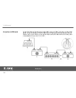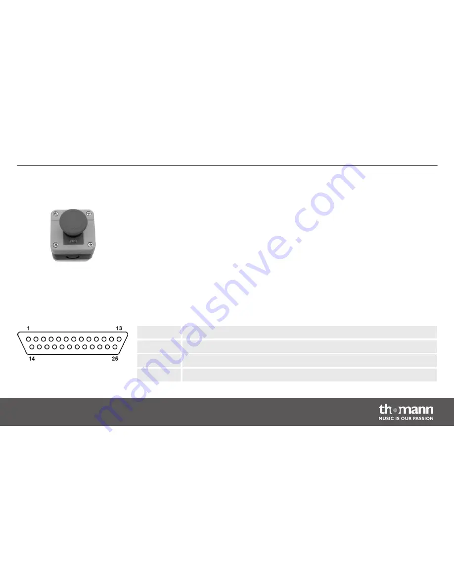
Connect the optional remote-control safety switch to the socket (7) of the device. An adapter
for switches with phone plug is included. If you press the switch, the laser beam is switched off
immediately. To unlock the switch and resume operation, turn the knob clockwise.
You can connect laser control units, that generate signals as standardized by the International
Laser Display Association to the ILDA input. The ILDA output of the unit can be connected to
other laser devices.
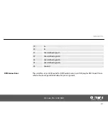
The ILDA interfaces are designed as 25-pin D-sub connectors. The drawing and table below
show the pin assignment.
1
X+
2
Y+
3
In
4
Locking (Interlock) A
Safety switch (emergency shut‐
down)
ILDA interface
Installation
DJ Lase Pro 1200 RGB
19
Summary of Contents for stairville DJ Lase Pro 1200 RGB
Page 1: ...DJ Lase Pro 1200 RGB showlaser user manual ...
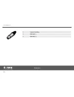
Page 22: ...1 Ground shielding 2 DMX data 3 DMX data Installation showlaser 22 ...
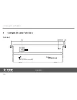
Page 26: ...6 Components and functions Front panel Components and functions showlaser 26 ...
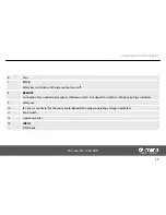
Page 28: ...Rear panel Components and functions showlaser 28 ...
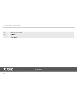
Page 30: ...14 SD memory card slot 15 OUTPUT DMX output Components and functions showlaser 30 ...
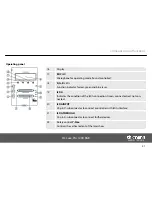
Page 39: ...7 3 Menu overview Operation DJ Lase Pro 1200 RGB 39 ...
Page 47: ...7 5 Pattern list Operation DJ Lase Pro 1200 RGB 47 ...
Page 48: ...Operation showlaser 48 ...
Page 49: ...Operation DJ Lase Pro 1200 RGB 49 ...
Page 59: ......
Page 60: ...Musikhaus Thomann e K Treppendorf 30 96138 Burgebrach Germany www thomann de ...

