16
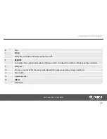
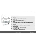
Display.
17
MIC LED
Microphone for operating mode ‘Sound controlled’.
18
R, G, B LEDs
Function indicator for red, green and blue laser.
19
ILDA
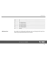
Indicates the condition of the ILDA connection. Green: connected; red: not con‐
nected.
20
ILDA INPUT
25-pin D-sub connector to connect a controller with ILDA interface.
21
ILDA THROUGH
25-pin D-sub connector to connect further devices.
22
Rotary control Y-Size
Controls the vertical extent of the laser show.
Operating panel
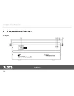
Components and functions
DJ Lase Pro 1200 RGB
31
Summary of Contents for stairville DJ Lase Pro 1200 RGB
Page 1: ...DJ Lase Pro 1200 RGB showlaser user manual ...
Page 22: ...1 Ground shielding 2 DMX data 3 DMX data Installation showlaser 22 ...
Page 26: ...6 Components and functions Front panel Components and functions showlaser 26 ...
Page 28: ...Rear panel Components and functions showlaser 28 ...
Page 30: ...14 SD memory card slot 15 OUTPUT DMX output Components and functions showlaser 30 ...
Page 39: ...7 3 Menu overview Operation DJ Lase Pro 1200 RGB 39 ...
Page 47: ...7 5 Pattern list Operation DJ Lase Pro 1200 RGB 47 ...
Page 48: ...Operation showlaser 48 ...
Page 49: ...Operation DJ Lase Pro 1200 RGB 49 ...
Page 59: ......
Page 60: ...Musikhaus Thomann e K Treppendorf 30 96138 Burgebrach Germany www thomann de ...

