DISASSEMBLY
NOTE: To avoid confusion, service one end of the compressor at a time.
STEP 1.
Clean loose dirt from the outside of the compressor.
STEP 2.
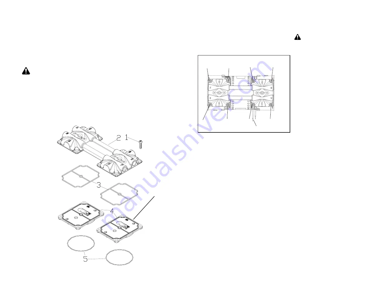
Loosen the 8 head screws (1) and remove the compressor head (2). Note orientation
of head and valve plates for reassembly (very important). Discard head screws.
Caution: Place capacitor off to side leaving it connected to
lead wires.
STEP 3.
Carefully remove the valve plates (4) from the bottom of the head, or cylinder
sleeves
STEP 4.
Remove the head gasket O-rings (3) and discard them. Turn the valve plates over.
Remove the valve plate O-rings (5) and discard them. Note orientation for reassembly.
1
Figure 1
Caution
To avoid property damage
or personal injury, always
try rotating the fan by HAND
prior to connecting the
unit to the power source.
Check for suction at the air
inlet port by placing your
finger over the port as you
turn the fan. You should
feel a slight suction with
each rotation of the fan. If
you don’t feel suction, or if
you feel or hear a thump as
you turn the fan, DO NOT
CONNECT THE UNIT TO A
POWER SOURCE; review
the assembly procedure for
possible error.
Numbers indicate tightening sequence
Power Leads
Head Assembly
5 3 7
1
4
6
2 8
STEP 2.
Place head on the valve plates, making sure the same letter orientation is
as it was before disassembly. Torque the head screws to 55 inch lbs. in a criss-cross
pattern.
STEP 3.
Push the fan guards into the housing until the release tabs “pop” into the
mounting holes in the compressor housing.
6
Note the tabs on
the valve plate
which indicate
exhaust side.


