4
STEP 14
. Rotate the rotor shaft so that flat faces up (12:00). Position piston cup at bot-
tom dead center of cylinder sleeve.
STEP 15.
Slide the connecting rod assembly onto the shaft until the eccentric face
positivly stops against the bearing. Align the eccentric setscrew with the flat of the shaft.
Rotate the eccentric and shaft 90 degrees so the set screw is visable through the access
hole in the housing, and tighten set screw to 125in•lbs.
STEP 16.
Align the flat on the fan with
the flat on the
motor shaft and slide the
fan back onto the motor shaft, making
sure you position the fan clip in the
same orientation as it was before you
removed it. Incorrect orientation of the
fan will not provide adequate cooling of
the compressor.
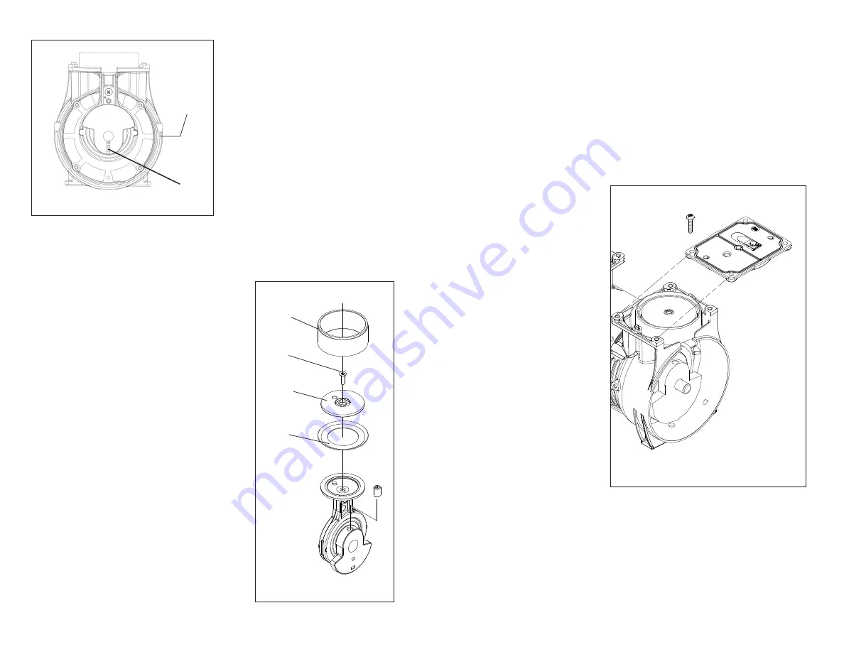
Figure 7
Hold the sleeve down against the
housing with one hand, and slowly
rotate the fan with the other hand to
ensure all components are lined up
properly. As the piston travels up and
down it will also rock from side to side.
This is a feature of the WOB-L Piston.
Repeat steps 9-16 on the other side of
compressor.
STEP 11
. Insert the 5/32” allen wrench into
the access hole in the compressor hous-
ing. Loosen the set screw 1/4 turn. Rotate
connecting rod to top dead center (180°)
and slide the connecting rod/eccentric
assembly off the shaft and through the
opening in the housing.
3
Eccentric
Set Screw
Access
Hole
Eccentric
Set Screw
Figure 5
STEP 12.
Secure the rod assembly in a fixture.
Remove the sleeve (1 - discard) from the con-
necting rod. Remove the screw (2 - discard )
from the cup retainer (3-retain for reassembly).
Remove the piston cup (4 - discard) and wipe
debris from the top of the connecting rod and
retainer with a clean damp cloth.
STEP 13
. Carefully place new sleeve (1) over
connecting rod top. Place new cup (4) in center
of connecting rod top. Do not damage the cup.
Place retainer (3) on top of cup (counterbore
up), making sure that the cup inside diameter
is seated properly over retaining boss. Note
that the retainer has a locating boss that must
insert into rod top pilot. Drive new retainer screw
to 100 in•lbs. Carefully push sleeve up forming
the cup. Stop pushing the cylinder sleeve up
when the piston cup is positioned midway inside
the sleeve.
1
4
3
2
Figure 6
CHECK OPERATION


