4
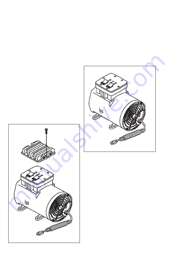
Figure #8
NOTE: The purpose of the following procedure is to correctly position the connecting
rod assembly on the the motor shaft before the Loctite
®
bond has dried.
STEP 4.
Hold the sleeve down against the housing with one hand, and slowly rotate
the eccentric with the other hand. As the piston travels up and down it will also rock
from side to side. This is a feature of the WOB-L Piston. If it rocks from front to rear, the
connecting rod is misaligned on the eccentric. If front to rear rocking is detected, loosen
the connecting rod clamping screw and repeat Steps 1, 2, and 3. If the connecting
rod cannot be properly aligned, contact the nearest service center.
STEP 5.
Install the new O-ring into the
bottom of the valve plate assembly,
seating it firmly into the groove with
your finger or blunt object.
STEP 6.
With the sleeve located and
firmly seated on the housing, replace
the valve plate as shown in Fig. #8.
Make sure the top edge of the cylinder
sleeve locates in the O-ring groove in
the bottom of the valve plate.
Figure #9
STEP 7.
Clean the inside of the head with
a soft clean cloth. Install the new gasket,
seating it firmly in the groove with your
finger or blunt object.
STEP 8.
Place the head on the top of the
valve plate. The exhaust fitting should be
facing the rear of the compressor, and
the smaller cavity inside the head will be
over the curved valve restraints on the
top of the valve plate. Install the 6 head
screws and tighten to 45 in-lbs. NOTE:
The handle, if present, should extend
over the exhaust fitting to provide proper
balance.


