background image

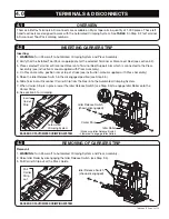
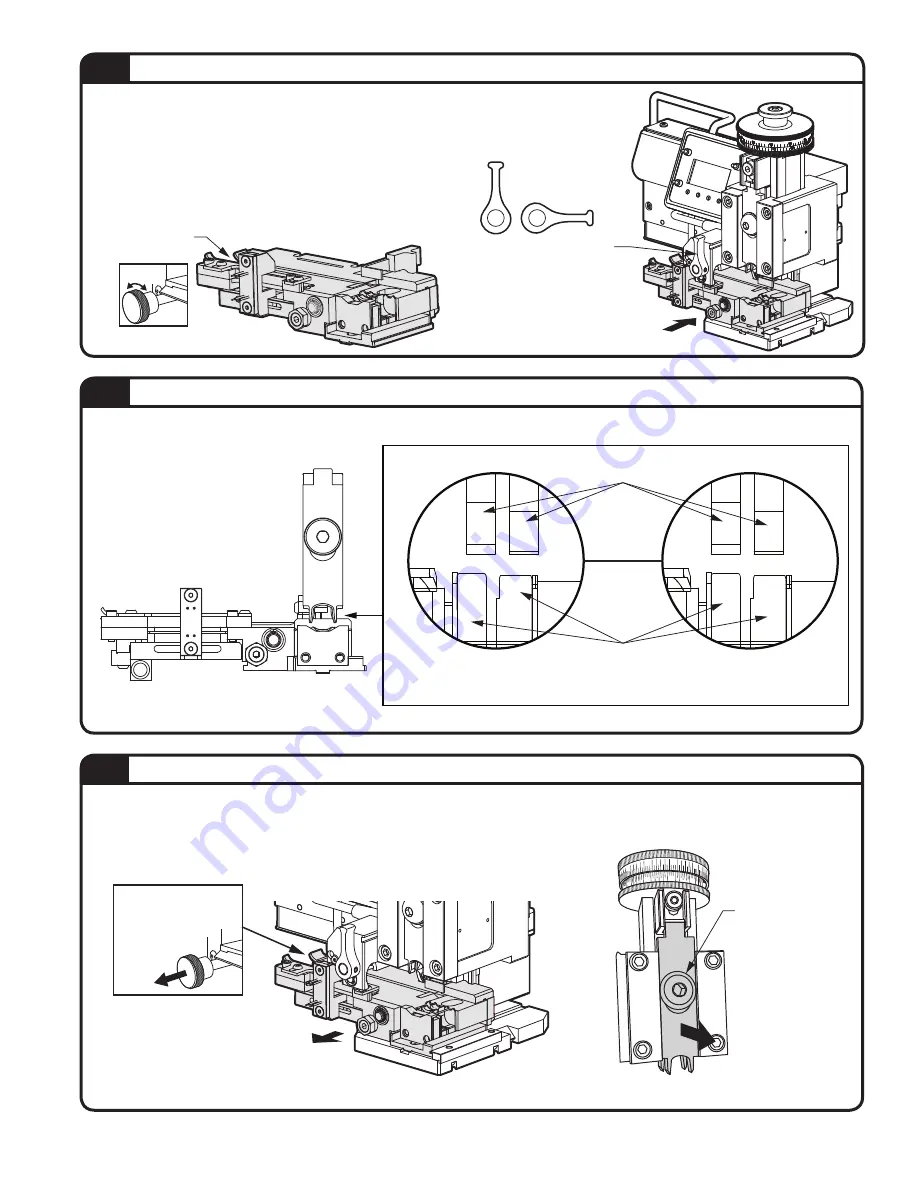
Pull Out

Pull Locking Pin
out to disengage.

Ram Fastener

unscrew with 

the supplied 

Hex Wrench

Pull Ram

Tool out.

1. Turn Power OFF to Electric Die and Press Assembly.
2. Remove Stock Guide by disengaging Idler Release Switch (Step 3.5). Disengage Locking Pin by pulling out 

Locking Pin and rotating into Locked position.

3. Remove Ram Tool by unscrewing Ram Fastener and pulling Ram Tool out.

Slide Stock Guide Out

Ram Tool

3.7

UN-INSTALLING TOOL PACKS

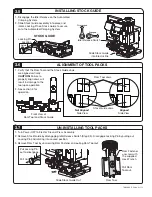
1. Verify that the Ram Tool and the Stock Guide Jaws 

are aligned vertically.   


CAUTION:

 Failure to 

properly align Jaws will 
result in damage to the 
tool upon operation.

2. See section 4 for 

operation.

Front View of

Ram Tool and Stock Guide

Aligned

Side View 

Not Aligned 

Side View

Ram Tool Jaws 

Stock Guide Jaws 

3.6

ALIGNMENT OF TOOL PACKS

STOCK GUIDE

3.5

INSTALLING STOCK GUIDE

1. Disengage the Idler Release on the Automated 

Crimping System. 

2. Slide Stock Guide assembly into place and 

rotate Locking Pin on Stock Guide to secure 
onto the Automated Crimping System.

Slide Stock Guide

into Electric Die

Disengaged

Idler Release Switch

Engaged

Locking Pin

Location

Rotate

TA04864  E   Page 4 of 13

Summary of Contents for QUICK-KON TNB170-ELECDIE

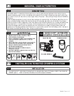
Page 1: ... Settings 6 6 0 SETTING ADJUSTMENTS Page 6 1 Feed Control 6 6 2 Run Mode 6 6 3 Speed Mode Calibration 7 6 4 Position Mode Calibration 7 6 5 Delay Mode Calibration 7 7 0 STOCK GUIDE Page 7 1 Wire Stop Adjustments 8 7 2 Terminal Sensor Adjustment 8 8 0 INDICATORS Page 8 1 Power Supply 9 8 2 Ram Sensor 9 8 3 Status LED s 9 9 0 SPECIFICATIONS Page 9 1 Cleaning 10 9 2 Inspection 10 9 3 Lubrication 10 1...

Page 2: ...nation The stepper motor driven pinch rollers engage the carrier strip and push the terminals into place for crimping Microprocessor based electronics in conjunction with sensors initiate a feeding cycle on the upward motion of the ram and control the stepper motor to precisely position the next terminal to be crimped A feed controller allows the operator to set feeding parameters electronically A...

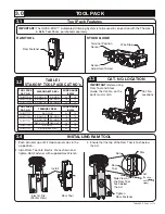
Page 3: ...LOCATION 3 3 3 2 TABLE I STA KON TOOL PACK CAT NO s TOOL PACK CAT NO DISCONNECT REEL WIRE RANGE AWG TNB177D01 RA NYLON RA VINYL 22 18 TNB177D02 RB NYLON RB VINYL 16 14 TNB177D03 RC NYLON RC VINYL 12 10 TOOL PACK CAT NO TERMINAL REEL WIRE RANGE AWG TNB177T01 RA NYLON 22 16 TNB177T02 RB NYLON RB VINYL 18 14 TNB177T03 RC NYLON RC VINYL 12 10 RBC NYLON RBC VINYL 16 12 TNB177T04 RA VINYL 22 16 TNB177T0...

Page 4: ...am Tool and the Stock Guide Jaws are aligned vertically CAUTION Failure to properly align Jaws will result in damage to the tool upon operation 2 See section 4 for operation Front View of Ram Tool and Stock Guide Aligned Side View Not Aligned Side View Ram Tool Jaws Stock Guide Jaws 3 6 ALIGNMENT OF TOOL PACKS STOCK GUIDE 3 5 INSTALLING STOCK GUIDE 1 Disengage the Idler Release on the Automated Cr...

Page 5: ... section 3 2 3 Place selected Terminal or Disconnect Reel onto Terminal Reel Support Arm which is connected to the Press Assembly see instruction manual supplied with Press Assembly 4 On Press Assembly position ram at top of stroke see instruction manual supplied with Press Assembly 5 Raise the Idler Release Switch in the disengaged position see Step 3 5 6 Slide Terminal or Disconnect Carrier Stri...

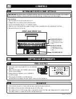
Page 6: ...ultaneously will display the total number of feed cycles completed 0 48 42 42 6 12 12 6 0 48 CONDUCTOR DIAL The higher the value is set the tighter the crimp will be INSULATION DIAL The higher the value is set the tighter the crimp will be DIAL INDICATOR CRIMP ADJUSTMENT DIAL IMPORTANT Recommended crimp height settings specific to terminal or disconnect tooling are provided with tool packs Before ...

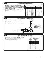
Page 7: ...s of the terminal disconnect relative to the tooling 2 Each value represents 0 001 of shift to the right or the left POSITION MODE CALIBRATION 6 4 Speed Selection Approximate Speed mm second Approximate Speed inches second 1 6 35 0 25 2 12 70 0 50 3 19 05 0 75 4 25 40 1 00 5 31 75 1 25 6 38 10 1 50 7 50 80 2 00 8 63 50 2 50 9 76 20 3 00 TABLE II 1 Set and adjust the Speed of the carrier strip duri...

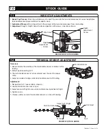
Page 8: ... screws 3 Adjust sensor left right to move terminal disconnect position left right 4 Tighten screw 5 Visually confirm center of terminal disconnect is in line with tooling TERMINAL SENSOR ADJUSTMENT 7 2 WIRE STOP ADJUSTMENTS 7 1 1 Bench Top Presses Wire stop will allow user to insert the wire into the terminal disconnect at correct depth See terminal disconnect documentation for depth value 2 Auto...

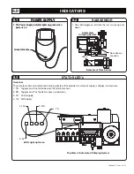
Page 9: ... pass the terminal sensor 2 RS Toggles on off as the Ram moves up and down 3 5V 5 Volt Supply 4 15V Volt Supply STATUS LED s 8 3 POWER SUPPLY 8 1 1 The Power Supply indicator lights up green when power is on 1 The LEDs toggle on off when the ram moves up and down Green Indicator Ram Sensor Location Automated Crimping System Example of Ram Sensor LED s RAM SENSOR 8 2 POWER SUPPLY 8 1 1 The Power Su...

Page 10: ...ANT Portions of the tooling that make contact during the crimping process are more prone to visual signs of wear INSPECTION 9 2 Recommended lubricant NLGI 2 Grade Lithium Complex EP grease or equivalent 1 Apply light coating of lubricant to each corner of the Ram 2 Apply a light coating of lubricant to each corner of the Ram Guide 3 Remove any excess lubricant and re insert Ram into Assembly LUBRI...

Page 11: ...g from 0 to 5 seconds Speed 9 selections ranging from 6 35 to 76 2 mm sec 0 25 to 3 0 in sec Position Offset from 12 7 mm in 0 024 mm increments 0 50 in 0 01 increments Crimp Heights Both Conductor and Insulator Range 1 0 mm 0 039 Max Adjustment Resolution 0 015 mm 0 005 Min Adjustment Power Requirements Single Phase AC 90 to 240 V 50 60 Hz Environmental Temperature 4 to 40 degrees Celsius 40 to 1...

Page 12: ...lots 3 Connect air lines REFER TO TNBDOC16 11 FOR WIRE GUIDE KIT LEFT TNBDOC16 12 FOR WIRE GUIDE KIT RIGHT MATING AIR CONNECTION QUICK COUPLER USE BF63 FOR M4 TUBE OR BF64 FOR M6 TUBE LEFT WIRE GUIDE KIT IS SHOWN LOCATE FUNNEL KIT WIRE GUIDE FOR SIZING SEE TABLE V ON PAGE 13 2 FUNNEL KIT ASSEMBLY 3 AIR LINES WIRE GUIDE SLOTS 1 WIRE GUIDE ASSEMBLY GUIDE PINS OPTIONAL RIGHT WIRE GUIDE KIT ...

Page 13: ... 098 0 109 0 122 0 028 034 0 035 042 0 043 0 048 0 049 0 060 0 069 0 076 0 089 0 098 0 109 0 122 Wire Guide Kit REF AWG Conductor Dia Wire Dia LEFT HAND ASSEMBLY 30 DEG LEAD IN TNBDOC16 11 Wire Guide Kit REF AWG Conductor Dia Wire Dia RIGHT HAND ASSEMBLY 30 DEG LEAD IN TNBDOC16 12 TNB189 018 TNB189 022 TNB189 025 TNB189 031 TNB189 039 TNB189 050 TNB189 062 TNB190 018 TNB190 022 TNB190 025 TNB190 0...

Reviews: