background image

DFT-6300 Battery Load Bank Instruction Manual


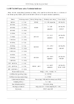
1.4 DFT-6300 Tester series Technical indicator 

  (Please  find  the  corresponding  parameters  according  to  the  actual  device  label,  this  table  is  a  collection  of 

conventional generic models, please check the label on the device for special customized parameters) 


Model 

Discharge current 

Battery String voltage 

Discharge end voltage 

Power supply 

24V50A 

0

50A 

DC24V 

10

30V adjustable 

AC220±15% 

48V150A 

0

150A 

DC48V 

10

60V 

adjustable 

AC220±15% 

DC48V 

48V200A 

0

200A 

48V300A 

0

300A 

110V20A 

0

20A 

DC110V 

98

121V 

adjustable 

AC220±15% 

DC110V 

110V60A 

0

60A 

110V100A 

0

100A 

220V30A 

0

30A 

DC220V 

176

275V 

adjustable 

AC220±15% 

DC220V 

220V50A 

0

50A 

220V100A 

0

100A 

220V160A 

0

160A 

380V20A 

0

20A 

DC380V 

304

456V 

adjustable 

AC220±15% 

DC380V 

380V50A 

0

50A 

380V100A 

0

100A 

80V

482V20A 

0

20A 

DC80V

482V 

80

482V 

adjustable 

AC220±15% 

DC80

482V 

80V

482V50A 

0

50A 

80V

482V100A 

0

100A 

Measurement accuracy 

Voltage

0.5%    Current

1% 

Cell-Data-Case operating voltage 

10

90VDC 

Cell-Data-Case measurement range 

0

15VDC 

Communication interface 

Data storage: USB parallel communication WI-FI 

Sampling interval 

5s

1min 

Heat dissipation method 

Forced air cooling 

Working environment   

Temperature

 0℃

50℃ & Humidity 5%

90% 

Screen size 

TFT-5’ color LCD 

Summary of Contents for DFT-6300

Page 1: ...DFT 6300 Battery Load Bank Users Manual THOMSONTECHCOLTD www thomsontesting com ...

Page 2: ...on 13 3 2 2 Voltage test line connection 14 3 2 3 Others 14 3 3 Cell Data Case connection 15 3 4 PC connection 18 3 5 Running 18 Chapter 4 Functions and operating procedures 19 4 1 Starting Boot 19 4 2 Discharge test 19 4 2 1 Checked capacity discharge 19 4 2 2 Battery discharge process 20 4 3 Data management 21 4 3 1 Data Query 21 4 3 2 Save to the U disk 22 4 3 3 Delete Data 22 4 4 System settin...

Page 3: ...smission cell voltage acquisition system can be short distance Wi fi communication transmission data data acquisition speed high precision strong anti interference ability easy to operate can record the battery discharge process of each time period of voltage changes effectively avoid the error caused by the connection and connection cable damage and other safety hazards Wi fi collection of cell v...

Page 4: ...tery voltage monitoring method Wi fi transmission cell voltage acquisition system each Wi fi transmission cell voltage acquisition system can simultaneously collect multiple sections of cell voltage and Wi fi send the testing results to the main device convenient for the construction of the test environment and measurement control and data distribution The discharge tester can monitor the single c...

Page 5: ... the THOMSON of the equipment under test Safety Information Security information is used to avoid casualties and damage to equipment Reading understanding and comply with the safety information and instructions in this instruction manual including follows Dangerous Indicates a very urgent and dangerous situation that could result in serious casualties if not avoided Warning Indicates a potentially...

Page 6: ... guidelines Make sure that the two battery clips are securely connected to the battery Battery explosions can cause casualties Warning Prevent burns The current generated by the battery short circuit is enough to melt down various ornaments and make them weld to metal So please remove various ornaments while working near the battery Any short circuit will result in injuries ...

Page 7: ...aintenance personnel and also improves the scientific and smart discharge test 1 2 Features The use of PTC ceramic resistors avoids the phenomenon of red heat and makes the whole discharge process safer With Wi fi communication function 3 device of Cell Data Case and Discharge host and monitoring PC three through Wi fi communication for Simplified wiring and flexible convenient The Wi fi Cell Data...

Page 8: ... discharge is automatically stopped and alarmed and the shutdown mode is automatically recorded Test discharge termination conditions can be set including cell battery voltage battery string termination voltage discharge current and discharge time Tester can record the discharge of each battery during the test discharge process mainly the total capacity of the battery string the total voltage the ...

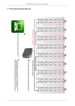
Page 9: ...DFT 6300 Battery Load Bank Instruction Manual 8 1 3 Working schematic diagram ...

Page 10: ...20A 0 20A DC110V 98 121V adjustable AC220 15 DC110V 110V60A 0 60A 110V100A 0 100A 220V30A 0 30A DC220V 176 275V adjustable AC220 15 DC220V 220V50A 0 50A 220V100A 0 100A 220V160A 0 160A 380V20A 0 20A DC380V 304 456V adjustable AC220 15 DC380V 380V50A 0 50A 380V100A 0 100A 80V 482V20A 0 20A DC80V 482V 80 482V adjustable AC220 15 DC80 482V 80V 482V50A 0 50A 80V 482V100A 0 100A Measurement accuracy Vo...

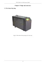
Page 11: ...DFT 6300 Battery Load Bank Instruction Manual 10 Chapter 2 Shape and structure 2 1 Host shape diagram Figure 2 1Host outline drawing image only for reference ...

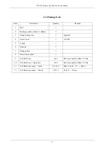
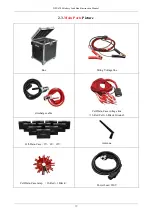
Page 12: ... String Voltage line 1 Optional 4 Power Lead 1 AC220V 5 U disk 1 6 Antenna 1 7 Package Box 1 8 Instruction manual 1 9 Cell Data Case 2set Each case match to Max 12 Cells 10 Cell Data Case voltage line 2kit Each case match to Max 12 Cells 11 Cell Data Case ramp Red 2 X 12 2 Max 12 Cells P Power 12 Cell Data Case ramp Black 2 X1 2 Cells P Power ...

Page 13: ...nk Instruction Manual 12 2 3 Main Parts Picture Box String Voltage line discharge cable Cell Data Case voltage line 12 Red Cell 1 Black Ground Cell Data Case 2V 6V 12V Antenna Cell Data Case ramp 12 Red 1 Black Power Lead 220V ...

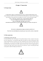
Page 14: ... and explosive materials around the work The air must not contain flammable and explosive gases to prevent the occurrence of explosions 3 2 Host connection 3 2 1 Discharge cable connection First connect the battery string discharge cable The large black discharge cable clip is connected to the negative pole of the battery string at one end and the quick plug at the other end to connect the black q...

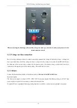
Page 15: ...of the DFT 6300 Tester the other end of the red test clip is connected to the positive pole of the battery string and the black test clip is connected to the negative pole of the battery string Be careful not to reverse 3 2 3 Others Connect the host antenna reliably to the antenna socket of the host of the DFT 6300 Tester Optional remarks The host power supply is normal AC22V if DC 200V host power...

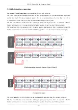
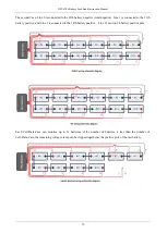
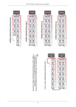
Page 16: ...egative total negative Line 1 is connected to the 1st battery positive and Line 2 is connected to the 2nd battery positive Line 12 section 12 battery cathode The second case Line 0 is connected to the 13th battery negative total negative Line 1 is connected to the 13th battery positive and Line 2 is connected to the 14th battery positive Line 12 section 24 battery positive pole The wiring harness ...

Page 17: ...nnected to the 13th battery positive and Line 2 is connected to the 14th battery positive Line 12 section 24 battery positive pole Each Cell Data Case can monitor up to 12 batteries if the number of batteries is less than the number of Cell Data Case the remaining voltage clamp can be clipped together at the positive pole of the last battery ...

Page 18: ...DFT 6300 Battery Load Bank Instruction Manual 17 ...

Page 19: ...PC is required Wi fi of Tester and PC needs to be connected 3 5 Running After checking that all wiring are correct turn on the power switch and after the LCD screen should be displayed normally you can complete the setting of various test discharge parameters according to the operating instructions ...

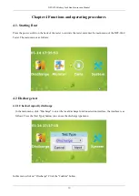
Page 20: ...he tester and enter the main menu of the DFT 6300 Tester The main menu is as follows 4 2 Discharge test 4 2 1 Checked capacity discharge In the main menu click Discharge to enter the local discharge function selection interface the interface is as follows Press the Test Type button you can see the discharge type menu In this menu click on Discharge Click the Confirm button ...

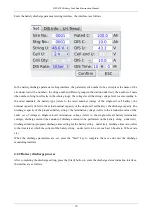
Page 21: ...ge capacity the discharge capacity of the proposed battery string the termination voltage refers to the termination value of the entire set of voltages Single cell cell termination voltage refers to the single cell cell battery termination voltage discharge current the amount of discharge current to be performed on the battery string under test discharge duration proposed discharge time setting fo...

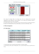
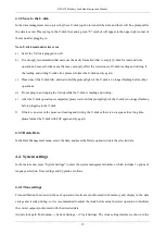
Page 22: ...ecovery status of each battery In the battery discharge interface the total battery voltage in the measured value area the discharge capacity is the capacity of the discharged battery string and the discharge current is the actual discharge current 4 3 Data management 4 3 1 Data Query 1 View the file data click Test Record on the main interface and enter the data list 2 Select the data you want to...

Page 23: ...ile the U disk is reading and writing e After the U disk operation is completed please wait until the prompt light of the U disk is no longer flashing before plugging in the U disk f If there is an error in the process of reading and writing the U disk or there is no response for a long time please format the U disk with FAT again and try again 4 3 3 Delete Data In the Data Management menu select ...

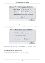
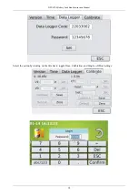
Page 24: ...n System Upgrade Press on the System Info menu item on the main menu page to view the DFT 6300 Tester system software version as shown in the figure When inserting a U disk containing upgrade files press the Upgrade button to upgrade the system 4 5 System Calibration Authorization Click System Settings on the main interface to enter the following interface ...

Page 25: ...DFT 6300 Battery Load Bank Instruction Manual 24 Select the action by clicking on the title bar to toggle Time Calibration and Single cell Box Settings ...

Page 26: ... alcohol etc so as not to damage the text on the host computer 5 1 2 Clamps Cleaning and maintenance Wash the clamps with a soft damp cloth and a mild detergent After cleaning wash it with clean water and dry it Do not scratch the metal part of the probe to avoid poor contact 5 2 Storage When used the host of the DFT 6300 Tester should be placed in the alloy box in time All parts and cables should...

Page 27: ...harge Please check the discharge parameter settings and the connection status of the battery wiring and voltage test line There is no display on the display after power on Check that the input power terminals are in good contact The keys are invalid or confused Please check if the key is stuck and not bouncing and if so you can return to normal work ...

Page 28: ...DFT 6300 Battery Load Bank Instruction Manual 27 Battery Data Management PC Software Manual THOMSON TECH CO LTD ...

Page 29: ...1 Software runtime environment 29 1 2 Software installation 29 1 3 Software uninstallation 29 1 4 Software running 30 1 5 Main Menu 30 Chapter 2 Data viewing and exporting to reports 31 2 1 Data Logger monitoring 31 2 2 Data viewing and importing old report 33 2 3 Export result to the report 35 2 4 Exit the software 37 ...

Page 30: ... the Microsoft NET exe on the U disk and double click to run Accept the terms and click Install as shown in the following figure Click Done PC Software installation Find the BTLStudioV1 3 4 on the U disk double click to run as shown in the following figure Click Next as shown below Select the corresponding installation path it is best not to install on the C disk the system disk does not have perm...

Page 31: ... Manual 30 1 4 Software running There are two ways to run the software 1 start program Battery Data management Software and click to run 2 Double click the icon of the Battery Data management Software desktop and start running 1 5 Main Menu ...

Page 32: ...d exporting to reports 2 1 Data Logger monitoring For the monitoring of the battery Data Logger the Site must be added before monitoring and the establishment process is shown in the following figure After adding site select the adding String as shown in the following figure ...

Page 33: ...DFT 6300 Battery Load Bank Instruction Manual 32 Select the sample data you want to view click View details or double click the data you want to view the interface pops up as below screenshot shown ...

Page 34: ... 2 Data viewing and importing old report Import Data Click the Import Data icon button pop up the interface select a file you can choose a file to import the import success will show success failure will prompt an error as shown in the following figure ...

Page 35: ...ual 34 Select the corresponding imported data double click or right click to view and a new interface will pop up as shown in the following figure After clicking the Save button you can see the actual data list as shown in the following figure ...

Page 36: ...DFT 6300 Battery Load Bank Instruction Manual 35 2 3 Export result to the report Click the Save Report button in the lower right corner as shown below ...

Page 37: ...cel or RTF format After the report export is completed the report will pop up in Sheet1 you can see the table header test units related parameters result statistics you can also see the histogram of each cell sheet2 is the detailed data of all Testing as shown in the following figure ...

Page 38: ...T 6300 Battery Load Bank Instruction Manual 37 2 4 Exit the software Click Close Report to exit the data report Click Close Recording to close the Data Logging page Click Exit System to close the software ...

Reviews: