ITC222 Geometry & Convergence Procedures
10
acceptable, geometry misalignment is indicated. That is because during sensor calibration
convergence is loaded with “neutral” values to make certain there is the least influence of
convergence while the circuit is attempting to find the screen sensors. Since the sensors are actually
located off-screen neutralizing convergence is the safest way to assure the sensors are found. When
Sensor Calibration fails, check the Event History. If the Test results indicate “Brightness” has
failed geometry is probably at fault. The geometry service menu may be used to make geometry
adjustments (See Geometry Procedures).
If the sensor calibration routine completes successfully, but autoconvergence fails, then one or
more convergence alignments are too far off for the autoconvergence amplifiers to correct. Once
sensor calibration completes and autoconvergence begins the convergence alignment points are
loaded with convergence values that are stored in the current mode EEPROM. If autoconvergence
fails at this point, the values that were in RAM are reloaded so the screen will have the original
appearance. The values in RAM may differ from the current mode EEPROM. Refer to Appendix
D, Field Service Menu to determine how to identify the color and area convergence stops on and
work on that specific area.
The ITC222 service adjustments are forgiving. In most cases it is not necessary to store adjustments
immediately!!! The service menu will remember the values before adjustments began allowing
the return to previous alignment values if necessary. Once alignments are verified to provide
acceptable performance, always return to the geometry menu and store the new values so they
become the defaults. Sensor calibration failure is also logged in the Event History screen of the
service menu. It will list the sensor number and color that failed during the sensor location routine.
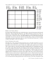
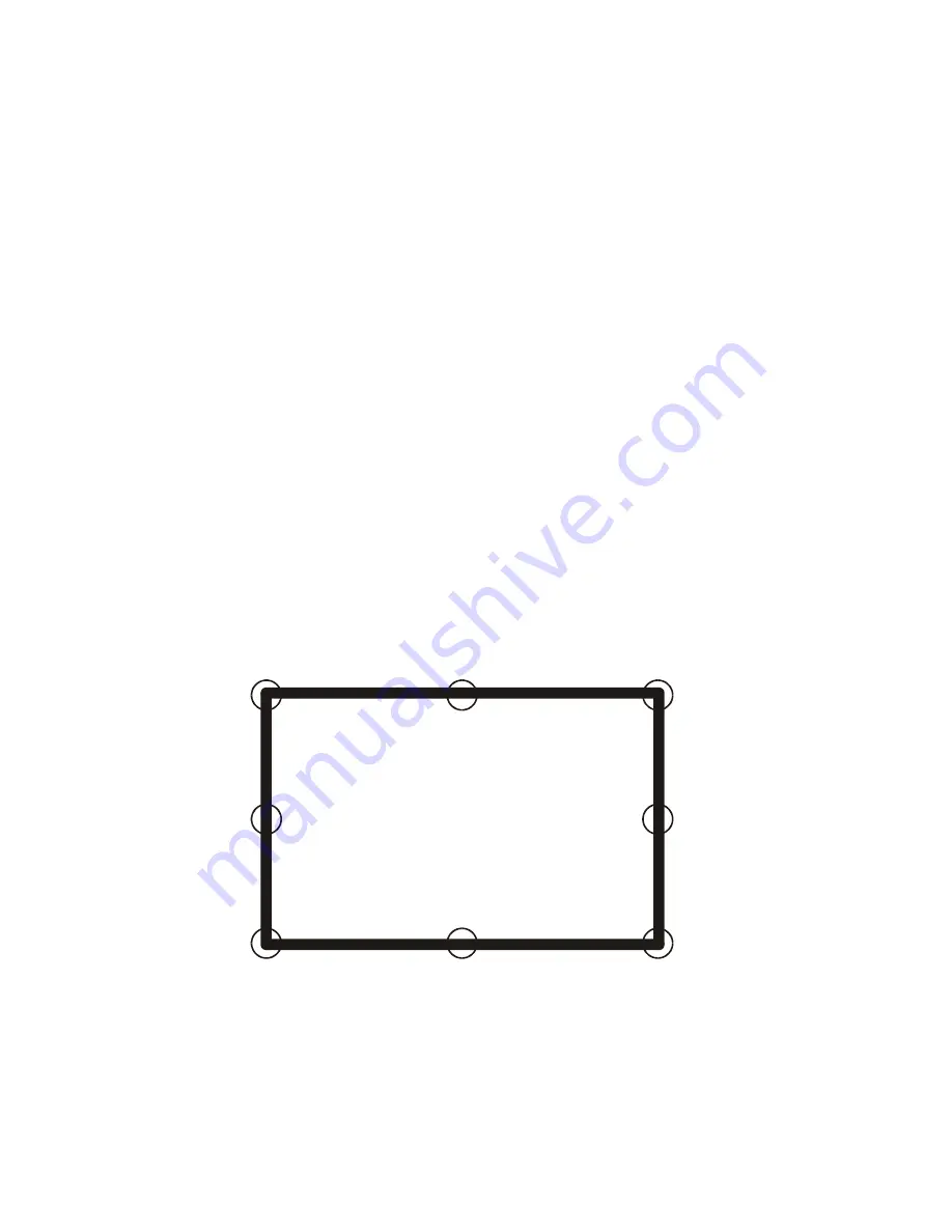
The location of the failure is also a reasonable clue as to where the problem is. The eight screen
sensors are located in order by color beginning with Red, then Blue, then Green. If there is a
failure of the red color in the first attempt chances are geometry is too far off. Noting which side
of the screen the sensor failed indicates which geometry adjustment should be made.
1
2
3
4
5
6
7
8
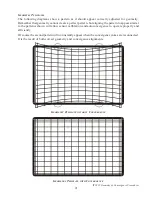
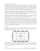
Remember there are 11 individual vertical points on each side of the screen and 13 horizontal
points on the top and 15 on the bottom of the screen plus one point on each corner that are actually
located “off” the screen. Those adjustments can actually drive the sensor position too far causing
autoconvergence to fail. That is the relationship between geometry and convergence. Both must
be successful for the complete autoconvergence routine to work.


