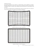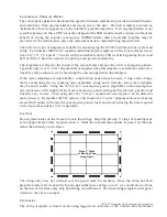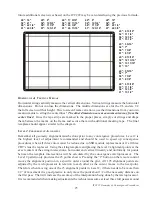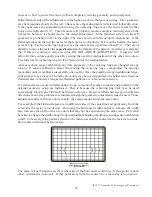
ITC222 Geometry & Convergence Procedures
13
EW-Trap
80
Adjusts the EW tilt of the raster
EW-Symmetry
70 (Default) Adjusts the right/left sides to be equal in tilt. Used sparingly.
EW-Up Corner
A4
Adjusts the upper corners right/left location
EW-Low Corner
90
Adjusts the lower corners right/left location
H-Parallel
70 (Default) Adjusts the right/left sides to be parallel.
Breathing
A0 (Default) Adjusts the effect of beam current on raster size. If excessive
breathing is noted when switching from dark to light scenes, make
adjustments two steps at a time until breathing is minimized.
Before attempting geometry adjustments, there are several steps that must be taken.
1. Connect the proper signals to place the instrument in the desired scan mode. (Remember
there are two scan modes, 480P, 2H and 1080I, 2.14H that must be aligned separately.)
480P will always be done first!!!
2. Enter the service menu from the standby mode by pressing and holding CH DN and VOL DN
for more than 8 seconds.
3. Select the proper input by pressing the “Input” button on the remote until the desired signal
is onscreen or select a channel by direct accessing it via the remote control.
4. In the service menu select Convergence Adjustments, Defaults and select the R/G/B Default.
This loads the default convergence alignments.
5. Return to the “Tube” menu and make certain the correct Tube Type is selected. The Tube
type may be confirmed by looking at the chassis service label. The Tube Type number will
appear in the format “P16LTG000RFA” where P16 is the tube size and the next three letters,
in this case “LTG” signify the Tube Type that will be selected in the Tube service menu.
6. Return to the “Geometry” menu and select “Vertical Slope”. The bottom half of the screen
will be blanked. With a test pattern onscreen that has center crosshairs, adjust until the
center horizontal line drops just below the visible part of the display. It may be easier to
block the red and blue patterns since Green is the only important pattern at this time.
7. Store the new setting by scrolling down to the “Store” selection and pressing “OK” on the
remote control.
The next steps depend on how far off geometry seems to be. If the prior SSB alignments were
uploaded into a replacement SSB geometry should be very close. Adjustments may be better made
by using the internal convergence pattern and an external crosshair or convergence block pattern.
If a CRT or main yoke has been replaced continue to the Centering Ring Adjustments. Otherwise
skip to the “Horizontal Position” setup.


