ITC222 Geometry & Convergence Procedures
24
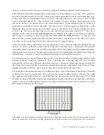
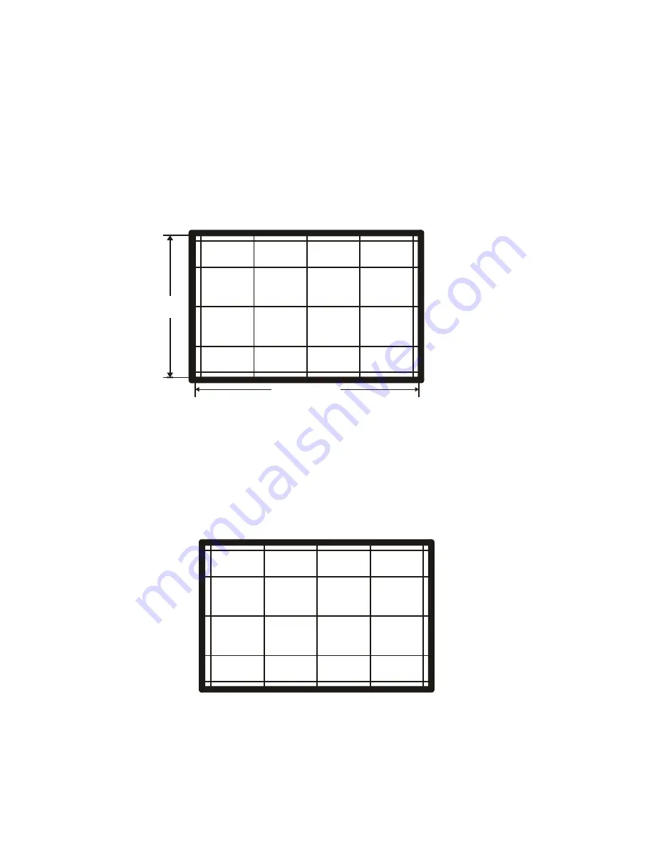
centerlines. There are two ways to accurately determine those locations. First the convergence
sensors may be located on the inside of the screen frame and a mark placed on the outer frame at
the location of the photosensor center. The photosensors are visible from the outside. The center
of the photosensor appears as a channel in the mounting bracket. Since the sensor calibration
routine relies on these sensors it is the most accurate way to locate the center lines.
Alternately the full distance between the right/left and top/bottom screen frames may be measured.
Use the inside of the frames, corresponding to only the visible area of the screen for this
measurement! Dividing those values in half gives the distance from any inside frame to the center
lines.
1/2 SCREEN WIDTH
CL
CL
1/2 SCREEN
HEIGHT
SCREEN WIDTH
SCREEN
HEIGHT
The centerlines should be marked and the first two strings representing the exact centerlines of the
visible picture area, placed on the screen. All further measurements will be calculated in relation
to these centerlines so their accuracy is important.
S
TRING
C
ALCULATIONS
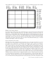
The remainder of the strings are measured away from the horizontal and vertical centerline. Those
measurements are the result of a precise formula shown in the following graphic.
CL
CL
CL
CL
0.54 x 1/2
Screen Height
0.54 x 1/2
Screen Height
0.456 x 1/2
Screen Width
0.456 x 1/2
Screen Width
0.456 x 1/2
Screen Width
0.456 x 1/2
Screen Width
0.912 x 1/2
Screen Width
0.912 x 1/2
Screen Width
0.912 x 1/2
Screen Width
0.912 x 1/2
Screen Width
0.54 x 1/2
Screen Height
0.54 x 1/2
Screen Height
0.90 x 1/2
Screen Height
0.90 x 1/2
Screen Height
0.90 x 1/2
Screen Height
0.90 x 1/2
Screen Height
The formula is the same for all screen sizes and is a constant ratio of screen width to screen height.
The following table shows the measurements for the 40”, 52”, 56” and 61” screen sizes. Any


