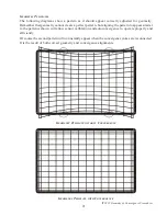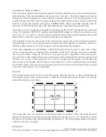
ITC222 Geometry & Convergence Procedures
25
future additional screen sizes based on the ITC222 may be calculated using the previous formula.
40": 17 9/16"
52": 22 11/16"
56": 24 3/8"
61": 26 11/16"
40": 8"
52": 10 5/8"
56": 11 1/8"
61": 12 3/16"
40": 8"
52": 10 5/8"
56": 11 1/8"
61": 12 3/16"
40": 16"
52": 21"
56": 22 1/4"
61": 24 3/8"
40": 16"
52": 21"
56": 22 1/4"
61": 24 3/8"
40": 9 13/16"
52": 12 13/16"
56": 13 11/16"
61": 15"
40": 5 5/16"
52": 7"
56": 7 3/8"
61": 8 1/8"
40": 5 5/16"
52": 7"
56": 7 3/8"
61": 8 1/8"
40": 8 13/16"
52": 11 1/4"
56": 12 3/8"
61": 13 1/2"
40": 8 13/16"
52": 11 1/4"
56": 12 3/8"
61": 13 1/2"
H
ORIZONTAL
& V
ERTICAL
S
TRINGS
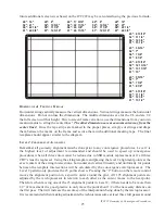
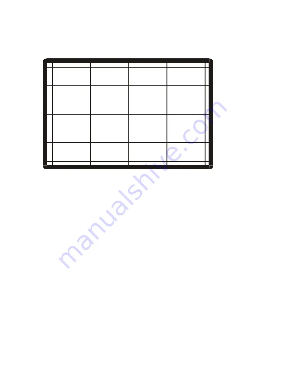
Horizontal strings actually measure the vertical dimensions. Vertical strings measure the horizontal
dimensions. Do not confuse the dimensions. The middle dimensions are for the CL and are 1/2
the full screen width or height. Due to screen frame variations, use the dimensions from your own
measurements to string the centerlines!
The other dimensions are measurements away from the
center lines!
Once the tape strips are marked in the proper places, simply cut strings and drape
them between the marks on the frame and secure them with additional masking tape. The final
template should appear similar to the diagram.
L
EVEL
2 C
ONVERGENCE
A
LIGNMENT
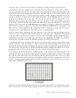
Remember all geometry alignment must be done prior to any convergence procedures. Level 2 is
the highest level of adjustment recommended and should be used to speed up convergence
procedures when all three colors must be redone due to SSB module replacement or if all three
CRT’s must be replaced. Using the string template and placing the level 2 alignment points at the
exact centers of the string intersections, horizontal and vertical linearity and uniformity for points
between the template intersections will be calculated by the convergence microprocessor. The
Level 2 pattern only provides the 25 points shown. Pressing the “2” button on the remote control
moves the alignment position in a specific order around the grid. All 195 alignment points are
adjusted by the microprocessor in relation to each other as the cursor moves to the next point.
Therefore when moving one of the 25 alignment points in Level 2, if there needs to be more than
1/2” of movement it is good practice to only move the point about 1/2 of the necessary distance on
the first pass. That will increase the accuracy of the interpolation being done by the microprocessor.
It is recommended when making adjustments the technician assume at least three full passes around


