ITC222 Geometry & Convergence Procedures
26
the screen are required to bring the pattern into a position for the final alignment in the Level 3
mode. Occasionally the interpolation routine makes errors in judgement. Be patient. Continue
going through the alignment routine until there appear to be no further improvements. At that
point, go to the Level 3 alignments for final adjustments. Always begin with green and complete
one color before going to the next. This assures a better template for comparison as convergence
proceeds.
L
EVEL
3 C
ONVERGENCE
A
LIGNMENT
Level 3 is the “fine tuning” mechanism for convergence. All 195 points are adjustable in all three
colors. There are no algorithms performed by the microprocessor however there are limits to the
adjustments.
The first limitation is that no two points can be closer together than geometrically allowed. If a
point moves too close to an adjacent adjustment, the adjacent adjustment will also begin moving
in an attempt to maintain the proper distance. If this is observed cease moving the point and find
out why the points are too close together. It may be necessary to go to the alignment point being
affected or even the next further point and relocate it. (See Hints & Tricks later in this manual.)
The second limitation is on the outermost DAC adjustment values. The DAC’s have a full
adjustment range of 255 steps designated differentially from 127-0-127. However the outermost
10% DAC range is limited reducing the effective range to around 110-0-110 or less depending on
the location of the adjustment. The 5x5 Level 2 adjustment range does not have this limitation on
itself but does prevent manual adjustment at the alignment points if the DAC is in the restricted
zone. In some cases if a Level 2 microprocessor adjustment left a DAC in that zone, the technician
may not be able to move it in the Level 3 adjustment. If there are several points that cannot be
moved in the Level 3 adjustments it indicates either the template is incorrect and several points are
not spaced correctly, or geometry could be misadjusted just to the point sensor calibration works,
but convergence is working too hard to provide a proper screen pattern. See Hints & Tricks later
in this section to correct the issue.
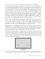
Another limitation is in the amplifiers themselves. If they must utilize excessive correction current
to bring an alignment to the proper grid point they may simply run out of power. That generally
appears similar to the following graphic.
Move Centering Rings
in Direction of Distortion
The amplifier has reached maximum deflection current causing the distinct plateau effect. The
proper adjustment location will probably never be reached however the flattened pattern may provide


