ITC222 Geometry & Convergence Procedures
28
C
ONVERGENCE
S
PECIFIC
F
UNCTIONS
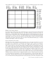
One pattern is available for convergence but the number of alignment points are determined by
which level is entered. The following table shows the number of alignment points and pattern
color available during manual convergence. Both are determined by the Level entered. When in
a Level 1, 2 or 3 of the Convergence Menu the OK button toggles through the pattern color as
noted below.
y
a
l
p
s
i
D
d
i
r
G
r
o
l
o
C
d
e
t
s
u
j
d
A
1
l
e
v
e
L
3
x
3
2
l
e
v
e
L
5
x
5
3
l
e
v
e
L
3
1
x
5
1
n
e
e
r
G
/
d
e
R
d
e
R
1
1
1
n
e
e
r
G
/
e
u
l
B
e
u
l
B
2
2
2
n
e
e
r
G
n
e
e
r
G
3
3
n
e
e
r
G
/
e
u
l
B
/
d
e
R
n
e
e
r
G
4
4
Notice Level 1 is limited to Red and Blue adjustment only. The OK button toggles back and forth
between the two. Again, the Level 1 adjustments are not recommended for any field service
circumstances!
Level 2 and Level 3 add two patterns. A full green grid allows course adjustment of the green
pattern in Level 2 and fine tuning in Level 3. There is also a full grid with all three colors available.
The three color pattern allows all three colors to be easily compared to each other. In the three
color pattern only green is adjustable. The OK button toggles through the colors as shown in the
table.
C
ONVERGENCE
EEPROM
EEPROMs are not fast devices. Therefore during normal chassis operation (including service
mode) all EEPROM convergence data is downloaded to the convergence RAM for use. Any changes
that are made by the technician during alignment efforts are done in RAM. The EEPROM values
are not changed until they are “stored’ by the technician. They will stay in RAM until AC power
is removed from the instrument or the next Autoconvergence is done.
If a technician converges an instrument but forgets to store it into EEPROM, the next time
power is removed or the consumer accesses and runs autoconvergence, convergence will return
to its state prior to the technician alignment efforts.


