ITC222 Geometry & Convergence Procedures
7
CRT R
EPLACEMENT
If one or more CRT’s have been replaced, always spend time realigning the yoke and centering
rings of the replacement(s) to existing CRT’s.
Do not touch
geometry and
do not adjust
the
convergence alignments of the CRT(s) not replaced. Centering and size are the two most important
mechanical alignments. Two video patterns are required; a full crosshatch pattern with known
horizontal and vertical centerlines and the internal convergence pattern. The results of these
procedures is to make certain the center crosshair lines of the replacement CRT are on top of the
existing CRT patterns and the raster is the same size and orientation.
The procedures for CRT replacement are:
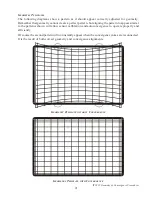
1. Once the CRT has been replaced, place the video pattern with full width and height center
crosshairs on the screen. Orient the center crosshair pattern vertically and horizontally by
rotating the yoke matching it with the CRT(s) not replaced.
2. Using the convergence pattern, determine the proper raster size by comparing the replacement
to the existing CRT patterns. Move the yoke up and down on the CRT neck until the size of
the replacement pattern matches the size of the existing patterns. Fix the yoke when size
and orientation are acceptable.
3. Still using the convergence pattern, if required use the “Centering Ring Setup” procedure
in the Geometry section, adjusting the centering rings to provide the proper alignment of
the crosshairs of the replacement to the existing CRTs. See the section on Geometry for
more detailed centering ring alignments.
4. This completes the CRT mechanical alignments. Electrical adjustments should not be
required.
5. In the Field Service Menu enter the Convergence menu. If convergence appears acceptable
run “Sensor Calibration”. If “Sensor Calibration” is successful, run autoconvergence and
again observe convergence. If it is acceptable repairs are complete. If it is not continue
with convergence procedures to realign the instrument.
SSB M
ODULE
R
EPLACEMENT
If convergence is required due to an SSB module replacement always attempt to download the
convergence alignments from the original SSB module. Refer to Appendix A, Chipper Check, for
the procedures. When the original settings are uploaded to the new SSB the convergence alignments
will not be perfect. However they will provide a better starting point than any default values
could. Before beginning realignment of convergence always check the “Tube Type” settings via
the service menu making certain it matches the CRT type of the instrument. Once the proper Tube
Type has been selected default values for first convergence and then geometry should be loaded.
There are several “fixed” values for geometry that should be set prior to geometry alignments. If
one or more CRTs have been replaced with the SSB, refer to the CRT Replacement procedures
making certain they are completed prior to doing any further convergence or geometry alignments.
Only then should the remainder of the geometry alignments be done. Once geometry is completed
may convergence be done. There are also instructions in the event the original alignments are not
available.


