background image

E N

5 5

0 1 9

0 0

0 0

0 0

0 0

0 3

0 0

0 2 0

0 2 1

0 2 3

0 2 2

E X I T

100-DVC00021

VGA

0 2 4

D P O F

C

E

A

X

N

E

M

C

C

E

E

U

M

L

T

O

E

RY MENU

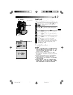
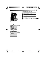
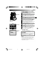
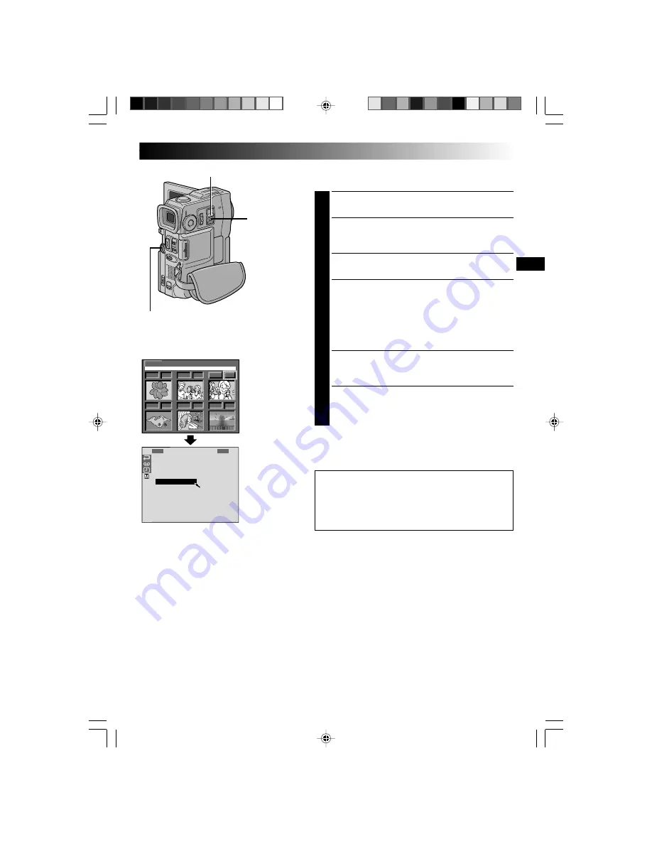
TO PRINT BY SELECTING STILL IMAGES
AND NO. OF PRINTS

1

Perform steps 

1

 through 

4

 on pg. 54.

2

Rotate the 

MENU 

wheel to selsect “SELECT” and

press it. Selection is complete. The DPOF Screen
appears.

3

Rotate the 

MENU 

wheel to move the green frame to

the image you wish to print and press it.

4

Select the number of prints by rotating the 

MENU

wheel towards “

+

” to increase the number, or

towards “

” to decrease the number and press it.

Repeat steps 

3

 and 

4

 for the desired number of prints.

•The number of prints can be set up to 15.
•To correct the number of prints, select the image

again and change the number.

5

Rotate the 

MENU 

wheel upward to select “EXIT” and

press it. Selection is complete. The Confirmation
Screen appears.

6

Rotate the 

MENU 

wheel to select “EXECUTE” and

press it. The normal playback screen appears.
•To cancel selection, rotate the 

MENU 

wheel to

select “CANCEL” and press it.

To Reset The No. Of Prints . . .

.... select “RESET” in step 

5

 on pg. 54. The number of

prints is reset to 0 for all still images.

MENU Wheel

DPOF Screen

NOTES:

If you load a MultiMediaCard already set as shown
above in a printer compatible with DPOF, it will make
prints of the selected still images automatically.

To print images recorded on a tape, first dub them to a
MultiMediaCard (

 pg. 65).

CAUTION:

While performing the above, never disconnect power,
as this may cause the memory to be corrupted. For
safety, all buttons including the 

POWER

 Switch are

disabled in step 

5

.

Display

Confirmation
Screen

POWER Switch

Lock Button

VMD22 EN(34/65)

29/08/00, 15:15

55

Summary of Contents for VMD22

Page 1: ...User manual VMD 22 35126140 vmd22 GB 1 08 00 14 23 Page Cov1...

Page 2: ...60 Dubbing From A VCR 61 Dubbing To A Video Unit Equipped With A DV Connector 62 Dubbing From A Video Unit Equipped With A DV Connector 63 Dubbing Images Stored In A MultiMediaCard To A Tape 64 Dubbi...

Page 3: ...not be able to get out No naked flame sources such as lighted candles should be placed on the apparatus When discarding batteries environmental problems must be considered and the local rules or laws...

Page 4: ...n the best results and safety is to be assured DO read the operating instructions before you attempt to use the equipment DO ensure that all electrical connections including the mains plug extension l...

Page 5: ...Capture JLIP Video Producer Picture Navigator for Windows CardNavigator Video Player Video Decoder AAA R03 Battery x 2 for remote control unit PC Connection Cable Editing Cable One plug has 3 rings ar...

Page 6: ...h the Menu Screen Rotate the MENU wheel to select OFF and press it The normal screen appears 1 R S Z S G B I D R E O O N A E D E E C U O A I E M C T N M P N P N O A U M D U M R O M U T M E N D M O P A...

Page 7: ...upplied to the camcorder and charging stops Since the AC Power Adapter Charger processes electricity internally it becomes warm during use Be sure to use it only in well ventilated areas When charging...

Page 8: ...Pack while sliding down BATT RELEASE detach it Power cord Approximate recording time BATT RELEASE Switch NOTES Recording time is reduced significantly under the following conditions Zoom or Record St...

Page 9: ...position 2 Pull out the viewfinder fully 3 Turn the Dioptre Adjustment Control until the indications in the viewfinder are clearly focused START STOP Button Power Zoom Lever Dioptre Adjustment Contro...

Page 10: ...ry To store the date time in memory the clock s rechargeable lithium battery is integrated in the camcorder While the camcorder is connected to an AC outlet using the AC Power Adapter Charger or while...

Page 11: ...t open close the cassette holder cover and try again If the cassette holder still does not open turn the camcorder off then on again If the tape does not load properly open the cassette holder cover f...

Page 12: ...wheel to select REC MODE and press it The Sub Menu appears Select SP or LP by rotating the MENU wheel and press it Rotate the MENU wheel to select 1RETURN and press it twice The Menu Screen closes Au...

Page 13: ...arked Some brands of MultiMediaCards are not compatible with this camcorder Before purchasing a MultiMediaCard consult its manufacturer or dealer To Unload A MultiMediaCard in step 3 push the MultiMed...

Page 14: ...the switch and set the MODE Dial to then open the LCD monitor fully The POWER lamp lights and the camcorder is turned on 2 Press IMAGE SIZE RES until the desired mode appears NOTES The number of stor...

Page 15: ...off the camcorder Allows you to play back a recording on the tape or to transfer a still image recorded on the tape or in the MultiMediaCard to a computer MEMORY PLAY Allows you to display an image s...

Page 16: ...to record moving images successive jitter free still images with superior quality on a tape pg 22 The still images can also be processed on a PC or printed out Zoom magnification over 10X is available...

Page 17: ...Grip Adjustment pg 8 Viewfinder Adjustment pg 8 Load A Cassette pg 10 Recording Mode Setting pg 11 1 Set the MODE Dial to VIDEO and set the POWER Switch to while pressing down the Lock Button located...

Page 18: ...appears when the tape reaches its end and the power goes off automatically if left in this condition for 5 minutes TAPE END also appears when a cassette at its end is loaded If the Record Standby mod...

Page 19: ...press during Recording PHOTO appears and a still image will be recorded for approx 6 seconds then the normal recording resumes To use the flash pg 30 Motor Drive Mode Keeping SNAPSHOT pressed provide...

Page 20: ...abled during Snapshot recording In such a case the icon blinks If shooting is not performed for approx 5 minutes when the POWER Switch is set to and power is supplied from the battery pack the camcord...

Page 21: ...pg 25 then zoom in or out in Record mode Zooming is possible to a maximum of 200X or it can be switched to 10X magnification using the optical zoom pg 27 Zoom magnification of over 10X is done through...

Page 22: ...shooting using a partially recorded tape When shooting on a blank portion located partway through the tape When shooting again after shooting a scene then opening closing the cassette holder cover Re...

Page 23: ...tor fully 2 To start Progressive Mode Recording press START STOP To End Progressive Mode Recording press START STOP The camcorder enters the Record Standby mode NOTES When an image recorded using the...

Page 24: ...between an odd and even Field when they are combined to make 1 Frame the part of the image that is moving appears as image jitter However during normal playback the moving picture looks smooth and na...

Page 25: ...elease SNAPSHOT snapshot recording will be cancelled 3 Press SNAPSHOT fully The displayed still image is stored in the MultiMediaCard NOTES If SNAPSHOT is pressed in the Record Standby mode only a sti...

Page 26: ...ct close to the lens zoom out first pg 20 If zoomed in in the auto focus mode the camcorder may automatically zoom out depending on the distance between the camcorder and the subject This will not occ...

Page 27: ...easy to use on screen menu system that simplifies many of the more detailed camcorder settings pg 27 29 1 Set the Operation Switch to and set the POWER Switch to while pressing down the Lock Button lo...

Page 28: ...rocessing and magnifying images zooming is possible from 10X the optical zoom limit to a maximum of 200X digital magnification Refer to Snapshot For Video Recording pg 18 Allows you to shoot dark scen...

Page 29: ...e subject as though it is moving pg 33 Usually the distance to a subject where the lens is in focus depends on the zoom magnification Unless there is a distance more than 1m to the subject the lens is...

Page 30: ...eeps the camcorder s display except the date time and time code from appearing on the connected TV screen Makes the camcorder s display appear on screen when the camcorder is connected to a TV Keeps t...

Page 31: ...HOT The flash fires twice The first flash is for reduction of the human eye s red reflection and the second flash is for the actual recording Display NOTES Do not fire the flash at a person at short r...

Page 32: ...viewfinder or open the LCD monitor fully 2 Press the MENU wheel The Menu Screen appears 3 Rotate the MENU wheel to select and press it MANUAL MENU appears 4 Rotate the MENU wheel to select FLASH ADJ a...

Page 33: ...ress it twice to close the Menu Screen 5 To engage the Self Timer for video recording press START STOP After 15 seconds the beep sounds and video recording starts To stop Self Timer recording press ST...

Page 34: ...ENU wheel to select 5S and press it 5S MODE appears 6 Press START STOP The tally lamp lights and beep sounds to indicate the start of recording and after 5 seconds the camcorder enters Record Standby...

Page 35: ...1 through 4 above 2 Engage the Record Standby mode If you select Picture Wipe Dissolve during recording press START STOP when one scene is finished The point at which the scene ended is stored in memo...

Page 36: ...wipe out from the top and bottom toward the centre leaving a black screen The new scene gradually appears as the old one gradually disappears The new scene wipes in over the previous one from the uppe...

Page 37: ...cording looks like a series of consecutive snapshots VIDEO ECHO 3 Adds a ghost to the subject giving your recording a fantasy feeling Zoom magnification of over 10X is not available SLOW Slow Shutter...

Page 38: ...ot be heard from the speaker during recording Use a headphone set to hear the sound effect To cancel recording the sound effect midway press DIGITAL SOUND again The camcorder stops recording the sound...

Page 39: ...0 P Iris lock indicator MENU Wheel POWER Switch Iris Lock Use this function in the following situations When shooting a moving subject When the distance to the subject changes so its size in the LCD m...

Page 40: ...when Sepia or Monotone pg 36 is activated Manual White Balance Operation Perform Manual White Balance when shooting under various types of lighting 1 Follow steps 1 through 4 of the white balance adj...

Page 41: ...e sound is not heard from the speaker Power Zoom Lever VOL Speaker MENU Wheel Still Playback Pauses during playback 1 Press 4 6 during playback 2 To resume normal playback press 4 6 again If still pla...

Page 42: ...nk portion of tape when you want to record from the middle of a tape pg 43 ON Enables dubbing of images recorded on a tape to a MultiMediaCard pg 65 OFF Enables snapshots to be taken during video play...

Page 43: ...detect the sound mode in which the recording was made during fast forward or rewind During playback the sound mode is displayed in the upper left corner SOUND MODE 12BIT MODE Factory preset STEREO SOU...

Page 44: ...linking and the camcorder automatically starts reverse or forward shuttle search then stops at the spot which is about 3 seconds of tape before the beginning of the detected blank portion To cancel Bl...

Page 45: ...l Clip Recording after step 3 press E MAIL CLIP REC again or press 5 to stop video playback To view video clips stored in a MultiMediaCard the video clip selected in the E CLIP Index Screen pg 47 Inde...

Page 46: ...nd 2 above 2 Press 4 6 If you press 2 during Auto Playback images are displayed in descending order If you press 3 during Auto Playback images are displayed in ascending order 3 To end Auto Playback p...

Page 47: ...he playback screen pg 45 the directory and only the last four digits of the file name are displayed 001 Index number Index numbers are marked from 001 For example when 10 files are stored index number...

Page 48: ...l Playback on pg 45 2 To access the Index Screen press INDEX once If you press INDEX twice the Index Screen for E Mail Clip Rec pg 44 appears if a video clip has been stored If there is no video clip...

Page 49: ...Rec PROTECT Index Screen select SOUND PRO to access the Sound Effect PROTECT Index Screen Then press the MENU wheel TO PROTECT A FILE Before doing the following perform steps 1 through 3 above 4 Rotat...

Page 50: ...the MENU wheel again The disappears 6 Rotate the MENU wheel upward to select EXIT and press it The Deletion Confirmation Screen appears 7 Rotate the MENU wheel to select EXECUTE and press it The sele...

Page 51: ...the LCD monitor fully or pull out the viewfinder fully 2 Press the MENU wheel The Menu Screen appears 3 Rotate the MENU wheel to select and press it MEMORY MENU appears 4 Rotate the MENU wheel to sel...

Page 52: ...nap frame is superimposed over the still image To Make The Snap Frame Disappear press SNAP FRAME NOTES A snap frame created on a PC can be transferred to a MultiMediaCard using the provided software T...

Page 53: ...lete and press it An appears above the selected snap frame Repeat this procedure for all snap frames that you wish to delete To deselect a snap frame press the MENU wheel again The disappears 7 Rotate...

Page 54: ...Y MENU TO DELETE ALL SNAP FRAMES 1 Perform steps 1 through 4 on pag 52 2 Rotate the MENU wheel to select ALL and press it The Deletion Confirmation Screen appears 3 Rotate the MENU wheel to select EXE...

Page 55: ...TO PRINT ALL STILL IMAGES ONE PRINT FOR EACH 1 Set the POWER Switch to MEMORY PLAY while pressing down the Lock Button located on the switch Open the LCD monitor fully or pull out the viewfinder fully...

Page 56: ...5 Rotate the MENU wheel upward to select EXIT and press it Selection is complete The Confirmation Screen appears 6 Rotate the MENU wheel to select EXECUTE and press it The normal playback screen appea...

Page 57: ...IDEO Yellow to VIDEO To S S Video cable optional Audio Video cable RCA plug to RCA plug optional Cable Adapter provided Set to Y C TV VCR Docking Station Attachment 1 Align the direction stud and scre...

Page 58: ...on to a TV or VCR equipped with an S VIDEO IN and or A V input RCA type connectors Audio Video cable RCA plug to RCA plug optional Red to AUDIO R IN TV VCR To S VIDEO IN Yellow to VIDEO IN Red to AUDI...

Page 59: ...he camcorder or Docking Station to your PC using the appropriate cable as shown in the illustration To attach the camcorder to Docking Station refer to Docking Station Attachment on pg 56 3 Turn the c...

Page 60: ...ion cable and the DV cable simultaneously to the camcorder Connect only the cable you wish to use to the camcorder The date time information cannot be captured into the PC Refer to the instruction man...

Page 61: ...ack Zoom pg 68 or Playback Special Effects pg 69 in step 5 Before you start dubbing make sure that the indications do not appear on the connected TV If they do they are being recorded onto the new tap...

Page 62: ...VCR s Play mode then engage the Still Playback mode when you have found a spot just before the edit in point 7 Press START STOP on the camcorder to engage the Record mode AV IN appears on the screen E...

Page 63: ...the battery pack pg 7 If the remote control is used when both the player and recorder are THOMSON video units both units will perform the same operation To prevent this from happening press the button...

Page 64: ...gage the Record mode DV IN appears on the screen Engage the video unit s Play mode 7 To stop dubbing press START STOP on the camcorder so that DV IN reappears then engage the video unit s Stop mode 8...

Page 65: ...age to be dubbed perform Index Playback pg 47 Auto Playback pg 45 or press 2 or 3 to select the image you wish 5 To engage Dub Standby press SNAPSHOT The message TO COPY TO TAPE PUSH SNAPSHOT appears...

Page 66: ...ate it to select ON and press it Selection is complete 5 Rotate the MENU wheel to select 1RETURN and press it twice The normal playback screen resumes 6 To select a video image to be dubbed start play...

Page 67: ...nt cover while pushing up the tab as illustrated 2 Insert two AAA R03 size batteries in the correct direction 3 Re attach the battery compartment cover USING THE REMOTE CONTROL UNIT When using the rem...

Page 68: ...beam signal Zoom in out pg 20 Functions the same as START STOP on the camcorder Functions the same as SNAPSHOT on the camcorder With the camcorder s POWER Switch set to or MEMORY PLAY Zoom in out pg...

Page 69: ...istur bances in video and the picture may seem unstable especially with steady images This is not a malfunc tion During Slow Motion Playback press PAUSE 6 to pause playback FEATURE Frame By Frame Play...

Page 70: ...s EFFECT The PLAYBACK EFFECT Select Menu appears 3 Move the highlight bar to the desired effect by pressing EFFECT The selected function is activated and after 2 seconds the menu disappears To deactiv...

Page 71: ...s the VCR s infrared sensor Then referring to the VCR CODE LIST press and hold MBR SET and press button A and then B The code is automatically set once you release MBR SET and the VCR s power comes on...

Page 72: ...DISPLAY on the remote control For GR DVX10 owners Make sure to set AV S VIDEO to OUT in the Menu Screen pg 41 When connecting the cables make sure to connect the ends with a core filter to the camcor...

Page 73: ...rough 9 to register additional scenes To change previously registered points press CANCEL on the remote control The registered points disappear one at a time from the most recently registered point If...

Page 74: ...e and the VCR enters its Record Pause mode If you do not register an Edit Out point the tape will be dubbed all the way to the end automatically If you operate the camcorder during automatic editing t...

Page 75: ...lay back the tape in the camcorder then point the remote control at the camcorder s remote sensor and press R A EDIT ON OFF The Random Assemble Editing Menu appears 2 Perform Random Assemble Editing o...

Page 76: ...advance the VCR s record timing by rotating the MENU wheel towards You can also delay the VCR s record timing by rotating the MENU wheel towards The adjustment range is from 1 3 to 1 3 seconds in 0 1...

Page 77: ...nal headphones to the AV OUT connector While an optional microphone is connected the built in microphone is disabled When editing onto a tape that was recorded at 12 bit the old and new soundtracks ar...

Page 78: ...Dubbing 4 Press DIGITAL SOUND where you want to use the sound effect The displayed sound effect blinks while it is being dubbed To stop dubbing the sound effect midway press DIGITAL SOUND again 5 Pre...

Page 79: ...void using strong cleaning agents such as benzine or alcohol Cleaning should be done only after the battery pack has been removed or other power units have been disconnected Mould may form if the lens...

Page 80: ...9 The 5 Second mode is set to ANIM in the Menu Screen 10 The Squeeze mode is selected 1 Connect the AC Power Adapter Charger securely pg 7 Replace the dead battery with a fully charged one pg 6 7 Ope...

Page 81: ...set to DUAL or P AE EFFECT is set to VIDEO ECHO in the Menu Screen WIDE MODE is set to PS WIDE in the Menu Screen Picture Wipe or Dissolve are being used in a scene transition 11 Set FLASH to ON in th...

Page 82: ...s normal but this slight delay becomes especially noticeable when shooting fast moving subject or during rapid panning 23 The Picture Wipe or Dissolve functions are in use WIDE MODE is set to SQUEEZE...

Page 83: ...MultiMediaCard are protected 31 ON SCREEN is set to SIMPLE or TIME CODE is set to OFF in the Menu Screen 32 In places subject to low temperature images become dark due to the characteristics of the L...

Page 84: ...er volume is too great 43 Since the analogue input mode is engaged the camcorder is in the Record Standby mode 44 35 Re read the sections covering Fade Wipe effects Programme AE with special effects a...

Page 85: ...unction 51 The DV cable was plugged unplugged with power turned on 52 53 45 Wipe them gently with soft cloth Wiping strongly can cause damage pg 78 46 Check the section of the manual that explains LCD...

Page 86: ...king Station s JLIP connector Then initialise or run the software again Auto Shut Off If 5 minutes elapse in the Record Standby mode or in the Pause mode the camcorder s power shuts off automatically...

Page 87: ...86EN INDEX Controls Connectors And Indicators O F O C U S B A C K L I G H T EXPOSURE 2 3 4 5 6 7 o u i 9 8 0 t Y U R E W e w Q T p d s r P a y I q VMD22 EN 66 100 29 08 00 15 47 86...

Page 88: ...IN OUT i link pg 58 59 62 63 i Link refers to the IEEE1394 1995 industry specification and extensions thereof The logo is used for products compliant with the i Link standard e Audio Video Output Con...

Page 89: ...on the camcorder pg 27 0 Displays the Time Code pg 21 29 Setting ON SCREEN to SIMPLE in the Menu Screen removes indications marked with from the screen pg 29 41 1 Displays the Picture Quality Size mo...

Page 90: ...S is engaged pg 28 9 Appears when the focus is adjusted manually pg 25 0 Approximate zoom ratio Appears during zooming pg 20 Appears when GAIN UP is set to AUTO and the shutter speed is automatically...

Page 91: ...LCD monitor or the viewfinder pg 16 VOLUME Displays the speaker or headphone volume pg 40 The level indicator moves 8 Displays the time code pg 41 42 1 L T 2 C B I 1 T 0 B V S L O 0 O E A L 6 U X N U...

Page 92: ...ars if a tape in another format is loaded Appears when the date time is not set pg 9 Appears when the built in clock lithium battery is discharged and the previously set date time is erased pg 9 Appea...

Page 93: ...been initialised Initialise the MultiMediaCard pg 50 Appears when the POWER Switch is set to MEMORY PLAY and there are no files stored in the MultiMediaCard Appears if there are no sound files stored...

Page 94: ...t short circuit the terminals do not modify or disassemble do not expose the battery to temperatures exceeding 60 C as this may cause the battery to overheat explode or catch fire use only specified c...

Page 95: ...where they won t be exposed to strong magnetic fields such as those generated by motors transformers or magnets LCD Monitor 1 To prevent damage to the LCD monitor DO NOT push it strongly or apply any...

Page 96: ...cleaning spray Do not bend the CD ROM or touch its mirror surface Do not store your CD ROM in a dusty hot or humid environment Keep it away from direct sunlight 4 To protect the unit DO NOT allow it t...

Page 97: ...ter Charger pg 6 7 Analogue Input pg 41 61 Animation pg 33 Audio Dubbing pg 76 Auto Date pg 29 Auto Focus pg 25 Auto Playback pg 45 Auto Shut off pg 17 19 40 B Backlight Compensation pg 38 Battery Low...

Page 98: ...S Self Recording pg 17 Self Timer pg 32 Sepia pg 36 Set Remote Control VCR Code pg 70 Shooting Mode DUAL pg 15 Shooting Mode DSC pg 15 Shuttle Search pg 40 Shutter Speed pg 36 Slow Motion Playback pg...

Page 99: ...Electronic viewfinder with 0 44 colour LCD Speaker Monaural For Digital Video Camera Format DV format SD mode Signal format PAL standard Recording Playback format Video Digital component recording Aud...

Page 100: ...prox 89 9 g For Connectors S Output Y 1 V p p 75 analogue C 0 29 V p p 75 analogue Input Y 0 8 V p p 1 2 V p p 75 analogue C 0 2 V p p 0 4 V p p 75 analogue VIDEO Video output 1 V p p 75 analogue Vide...

Page 101: ...100EN NOTES VMD22 EN 66 100 29 08 00 15 48 100...

Page 102: ...A Le Gallo 92648 Boulogne Cedex France RCS NANTERRE B 322 019 464 http www thomson multimedia com 35126140 LYT0662 001A Copyright THOMSON multimedia 2000 DAE Communication 95000 Cergy 35126140 vmd22...

Reviews: