389
Appendices
© 2010 Thorlabs
10.1.1.3
Flange Back Distance
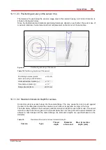
10.1.1.3.1 Calculation of the flange back distance
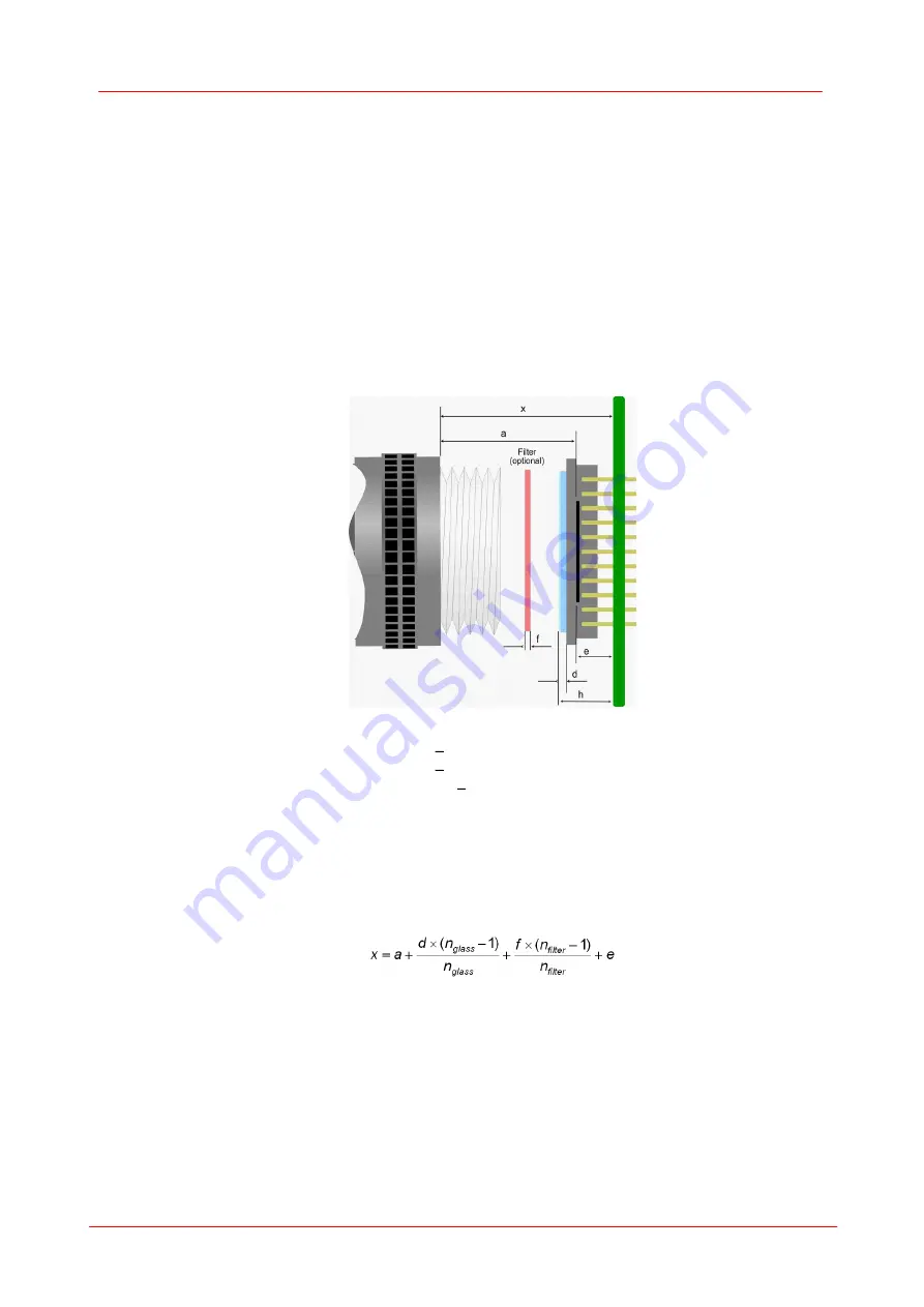
To correctly determine the flange back distance of a DCx camera, you need to consider the distance
between the lens flange and the active area of the sensor and, additionally, the type and thickness of
any materials inserted into the optical path.
The distance in air between the threaded flange and the active area is 17.526 mm with C-mount
lenses and 12.526 mm with CS-mount lenses.
This mechanical distance can change due to the material-specific refractive index of the inserted
materials. The glass cover of the sensor and all filters inserted into the optical path must be taken
into account in the calculation.
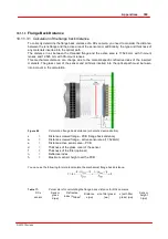
Figure 86
Calculation flange b ack distance (schematic demonstration)
x
=
Distance screwed flange PCB (flange back distance)
a
=
Distance screwed flange active sensor area (17,526mm)
e
=
Distance active sensor area PCB
d
=
Thickness of the glass cover of the sensor
f
=
Thickness of the filter (optional)
n
=
Refractive index
h
=
Maximum sensor height over the PCB
You can use the following formula to calculate the mechanical flange back distance:
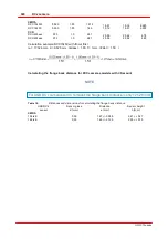
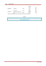
Table 17:
Parameters for calculating the flange b ack distance for DCx cameras
DCx
sensor
Sensor
glass
d
[mm]
Refractive
index (n
Glass
)
Distance
e
[mm]
x (no filter glass)
[mm]
x (with filter
glass)
[mm]
Sensor
height
h
[mm]
Summary of Contents for DCC1 45 Series
Page 5: ...Version Date 3 5 2 22 09 2010 2010 Thorlabs 2010 Thorlabs ...
Page 13: ......
Page 15: ......
Page 16: ...Introduction DCx camera Part I ...
Page 18: ...General Information DCx camera Part II ...
Page 21: ......
Page 22: ...Getting Started DCx camera Part III ...
Page 24: ...Installation DCx camera Part IV ...
Page 30: ...uc480 Camera Manager DCx camera Part V ...
Page 38: ...Camera viewer uc480Viewer DCx camera Part VI ...
Page 45: ...40 DCx camera 2010 Thorlabs Menu Help Figure 15 Info about Camera viewer uc480Viewer ...
Page 87: ......
Page 88: ...SDK Software development Kit DCx camera Part VII ...
Page 109: ...104 DCx camera 2010 Thorlabs Figure 52 Flowchart Handling events messages ...
Page 121: ...116 DCx camera 2010 Thorlabs Flowchart Digital output Figure 57 Flowchart Digital output ...
Page 161: ...156 DCx camera 2010 Thorlabs Related Functions is_GetCameraType is_CameraStatus 159 121 ...
Page 175: ...170 DCx camera 2010 Thorlabs is_GetExposureTime 167 ...
Page 238: ...233 SDK Software development Kit 2010 Thorlabs is_SetImagePos is_SetPixelClock 271 277 ...
Page 261: ...256 DCx camera 2010 Thorlabs is_SetTriggerDelay 289 ...
Page 271: ...266 DCx camera 2010 Thorlabs is_SetGainBoost is_SetAutoParameter 261 221 ...
Page 283: ...278 DCx camera 2010 Thorlabs is_SetSubSampling is_SetAOI 284 219 ...
Page 291: ...286 DCx camera 2010 Thorlabs is_SetAOI is_SetImagePos is_SetPixelClock 219 271 277 ...
Page 361: ......
Page 362: ...Maintenance and Service DCx camera Part VIII ...
Page 370: ...365 Maintenance and Service 2010 Thorlabs ...
Page 371: ......
Page 372: ...Camera Basics DCx camera Part IX ...
Page 389: ......
Page 390: ...Appendices DCx camera Part X ...
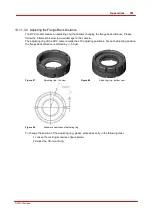
Page 397: ...392 DCx camera 2010 Thorlabs Figure 90 Securing the adjusting ring ...
Page 405: ...400 DCx camera 2010 Thorlabs Figure 106 Rev 2 0 Flash Strobe output as Open Emitter OE ...
Page 420: ......

