398
DCx camera
© 2010 Thorlabs
10.1.3
I/O Interface
10.1.3.1
Trigger Input Wiring (Trigger)
NOTE
The USB Board Rev. can be read out with the Camera Info
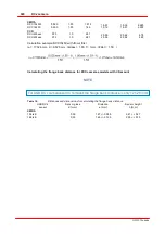
Table
21
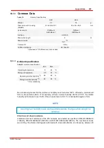
Digital input specifications
USB board revision
*
)
1.2
2.0 or higher
Min.
Max.
Min.
Max.
Level low
0
2
0
2
V
Level high
9
24
5
24
V
Voltage range
0
30
0
30
V
Trigger pulse width (edge)
100
-
100
-
µs
Trigger edge steepness
35
35
V/ms
Breakdown voltage
50
50
V
Input current
10
-
10
-
mA
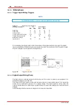
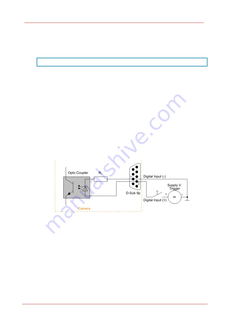
For interpreting the trigger signal, either the positive or the negative edge can be used. The digital
input is galvanically isolated using an opto coupler to protect the camera and the PC against surges.
Only DC voltages may be applied to the digital input.
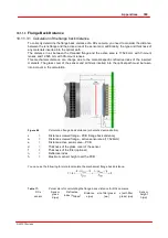
Figure 102
Trigger connection
10.1.3.2
Digital Output Wiring (Flash)
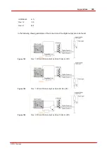
The flash strobe is optically isolated to DCU and your PC on order to protect your equipment. It is
adapted for voltages up to 24V DC.
The output of the opto coupler can be used as open collector or open emitter output. This means the
strobe can be switched to ground or to a supply voltage. The strobe signal is active, when the
collector emitter switch is closed. Opto couplers solely can switch DC voltages. Do never switch AC
voltages.
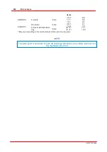
In the following table the maximum charges for the output are specified.
Summary of Contents for DCC1 45 Series
Page 5: ...Version Date 3 5 2 22 09 2010 2010 Thorlabs 2010 Thorlabs ...
Page 13: ......
Page 15: ......
Page 16: ...Introduction DCx camera Part I ...
Page 18: ...General Information DCx camera Part II ...
Page 21: ......
Page 22: ...Getting Started DCx camera Part III ...
Page 24: ...Installation DCx camera Part IV ...
Page 30: ...uc480 Camera Manager DCx camera Part V ...
Page 38: ...Camera viewer uc480Viewer DCx camera Part VI ...
Page 45: ...40 DCx camera 2010 Thorlabs Menu Help Figure 15 Info about Camera viewer uc480Viewer ...
Page 87: ......
Page 88: ...SDK Software development Kit DCx camera Part VII ...
Page 109: ...104 DCx camera 2010 Thorlabs Figure 52 Flowchart Handling events messages ...
Page 121: ...116 DCx camera 2010 Thorlabs Flowchart Digital output Figure 57 Flowchart Digital output ...
Page 161: ...156 DCx camera 2010 Thorlabs Related Functions is_GetCameraType is_CameraStatus 159 121 ...
Page 175: ...170 DCx camera 2010 Thorlabs is_GetExposureTime 167 ...
Page 238: ...233 SDK Software development Kit 2010 Thorlabs is_SetImagePos is_SetPixelClock 271 277 ...
Page 261: ...256 DCx camera 2010 Thorlabs is_SetTriggerDelay 289 ...
Page 271: ...266 DCx camera 2010 Thorlabs is_SetGainBoost is_SetAutoParameter 261 221 ...
Page 283: ...278 DCx camera 2010 Thorlabs is_SetSubSampling is_SetAOI 284 219 ...
Page 291: ...286 DCx camera 2010 Thorlabs is_SetAOI is_SetImagePos is_SetPixelClock 219 271 277 ...
Page 361: ......
Page 362: ...Maintenance and Service DCx camera Part VIII ...
Page 370: ...365 Maintenance and Service 2010 Thorlabs ...
Page 371: ......
Page 372: ...Camera Basics DCx camera Part IX ...
Page 389: ......
Page 390: ...Appendices DCx camera Part X ...
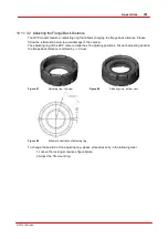
Page 397: ...392 DCx camera 2010 Thorlabs Figure 90 Securing the adjusting ring ...
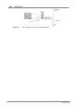
Page 405: ...400 DCx camera 2010 Thorlabs Figure 106 Rev 2 0 Flash Strobe output as Open Emitter OE ...
Page 420: ......


