377
Camera Basics
© 2010 Thorlabs
9.10
Color filter (Bayer filter)
For technical reasons digital image sensors can only detect light intensity, but no color information.
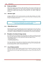
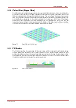
To produce color sensors a color filter is applied on each photocell (pixel). The pattern of the color
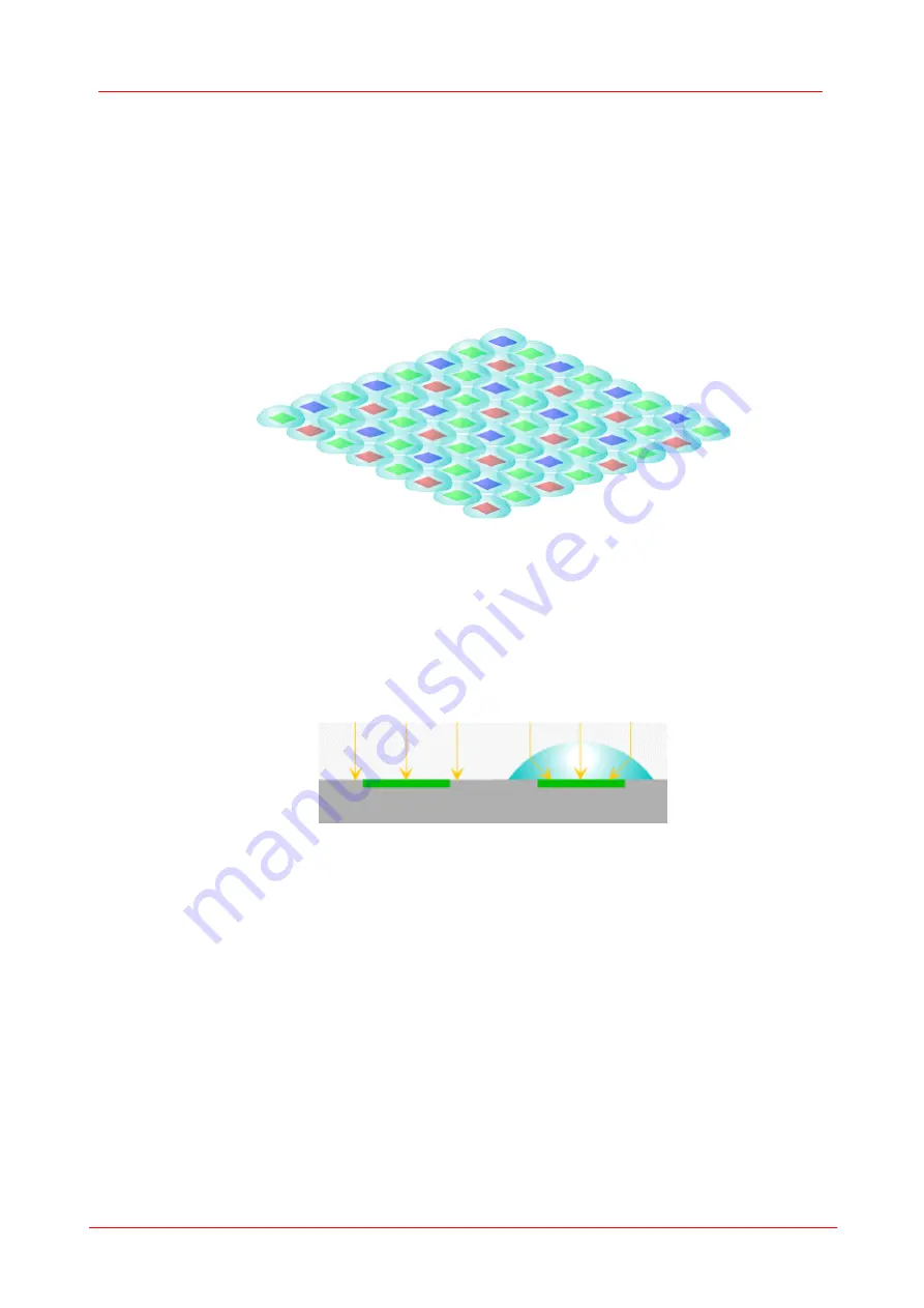
filters is illustrated in Fig. 9: Bayer-filter and micro lenses. Two out of every four pixels have a green
filter, one pixel has a red filter and one has a blue filter applied. This pattern is called Bayer filter. The
color distribution corresponds to the color sensitivity of a human eye. With help of the Bayern
pattern the correct brightness and color information can be calculated for each pixel. The full
resolution of sensor is kept. Color conversion into Y8-, RGB- or YUV-format can be done at run-time
in the PC with the functions of the DCU software development kit (SDK).
Figure 73
Bayer-filter and mcro lenses
9.11
Fill factor
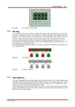
The fill factor specifies the percentage of the sensor area which is exposed to light during image
capture. Ideally this would be 100 %. Other elements on the sensor surface beside the light
sensitive photodiodes reduce this value. Depending upon sensor technology the percentage is only
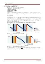
around 30-50%. The use of micro lenses raises the fill factor to up to 70 %. The micro lenses collect
the light on a photocell and increase the usable sensor area.
Figure 74
Use of micro lenses
Summary of Contents for DCC1 45 Series
Page 5: ...Version Date 3 5 2 22 09 2010 2010 Thorlabs 2010 Thorlabs ...
Page 13: ......
Page 15: ......
Page 16: ...Introduction DCx camera Part I ...
Page 18: ...General Information DCx camera Part II ...
Page 21: ......
Page 22: ...Getting Started DCx camera Part III ...
Page 24: ...Installation DCx camera Part IV ...
Page 30: ...uc480 Camera Manager DCx camera Part V ...
Page 38: ...Camera viewer uc480Viewer DCx camera Part VI ...
Page 45: ...40 DCx camera 2010 Thorlabs Menu Help Figure 15 Info about Camera viewer uc480Viewer ...
Page 87: ......
Page 88: ...SDK Software development Kit DCx camera Part VII ...
Page 109: ...104 DCx camera 2010 Thorlabs Figure 52 Flowchart Handling events messages ...
Page 121: ...116 DCx camera 2010 Thorlabs Flowchart Digital output Figure 57 Flowchart Digital output ...
Page 161: ...156 DCx camera 2010 Thorlabs Related Functions is_GetCameraType is_CameraStatus 159 121 ...
Page 175: ...170 DCx camera 2010 Thorlabs is_GetExposureTime 167 ...
Page 238: ...233 SDK Software development Kit 2010 Thorlabs is_SetImagePos is_SetPixelClock 271 277 ...
Page 261: ...256 DCx camera 2010 Thorlabs is_SetTriggerDelay 289 ...
Page 271: ...266 DCx camera 2010 Thorlabs is_SetGainBoost is_SetAutoParameter 261 221 ...
Page 283: ...278 DCx camera 2010 Thorlabs is_SetSubSampling is_SetAOI 284 219 ...
Page 291: ...286 DCx camera 2010 Thorlabs is_SetAOI is_SetImagePos is_SetPixelClock 219 271 277 ...
Page 361: ......
Page 362: ...Maintenance and Service DCx camera Part VIII ...
Page 370: ...365 Maintenance and Service 2010 Thorlabs ...
Page 371: ......
Page 372: ...Camera Basics DCx camera Part IX ...
Page 389: ......
Page 390: ...Appendices DCx camera Part X ...
Page 397: ...392 DCx camera 2010 Thorlabs Figure 90 Securing the adjusting ring ...
Page 405: ...400 DCx camera 2010 Thorlabs Figure 106 Rev 2 0 Flash Strobe output as Open Emitter OE ...
Page 420: ......

