background image

ELL9K Four-Position Slider Evaluation Kit


Chapter 3: Installation 

Rev. C, Feb 2020 


Page 5


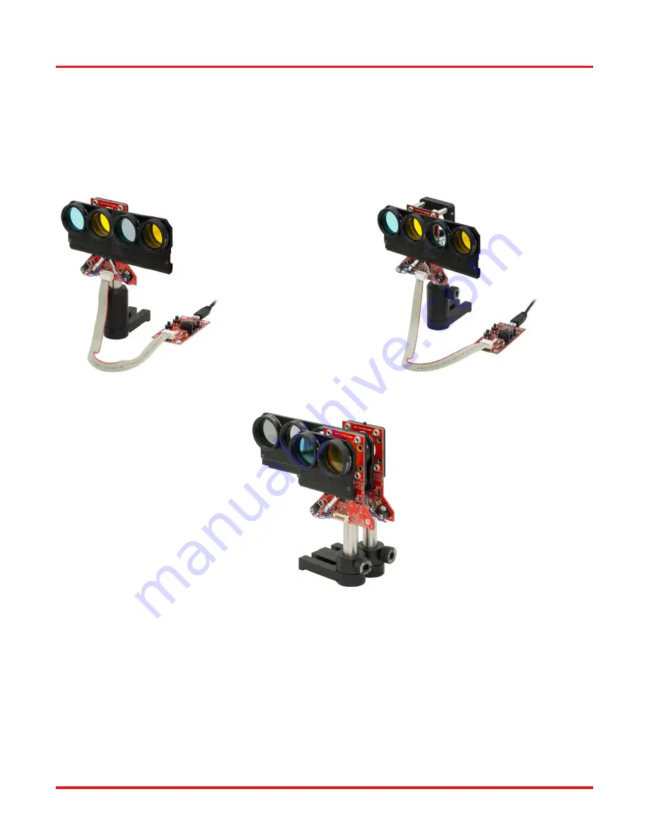
There are several options for mounting the sliders. The ELLA1 Post Mount Adapter, which is available below, has a 14.0 mm 
width and fastens directly to the back of the slider's PCB. As shown in Figure 2, the adapter can then be used to mount the 
slider to a Ø1/2" post. The compact dimensions of the ELLA1 allows sliders to be placed one behind the other while minimizing 
the space separating them, as shown below. The adapter can also be integrated with Thorlabs' 30 mm Cage System 
components and/or SM1-threaded components, such as lens tubes. Alternately, 30 mm cage system components alone can 
be used to mount the sliders. An example of this is shown in Figure 3, in which a CP02 Cage Plate, four ER1 rods, a Ø1/2" 
post, and a post holder mount and support the assembled ELL9K. 


Figure 2 ELL9 mounted using ELLA1  


 Figure 3 ELL9 mounted using 30 mm cage rods 


Figure 4 Close mounting of ELL6 and ELL9 using ELLA1 


Summary of Contents for ELL9

Page 1: ...ELL9K Four position Slider Evaluation Kit HA0386T ELL9 K Four Position Slider Kit Operating Manual Original Instructions ...

Page 2: ... 4 Connecting Multiple Devices 9 4 2 5 Controlling the stage without the handset 9 Periodic Cycling of Devices Over Full Range of Travel 11 Frequency Search 11 Restoring Factory Settings 11 Simultaneous Movement of Devices 12 Chapter 5 Troubleshooting and FAQ 13 Frequently Asked Questions 13 Notes on Making a Picoflex Cable for Use when Daisy Chaining Devices 14 Chapter 6 Specifications 16 Chapter...

Page 3: ...ts a multi drop serial communication protocol and a set of digital IO lines allows the user to control the movement and state manually by switching the lines high 5V or low 0V The slider features four mounting positions for SM1 optics It can be post mounted using our ER series cage system rods and a CP02 M Cage Plate see Section 3 2 It is also compatible with 30 mm cage systems It offers 93 mm 3 6...

Page 4: ... used in a manner not specified by the manufacturer the protection provided by the equipment may be impaired In particular excessive moisture may impair operation The equipment is susceptible to damage from electrostatic discharge When handling the device anti static precautions must be taken and suitable discharge appliances must be worn Spillage of fluid such as sample solutions should be avoide...

Page 5: ...t 31 C To ensure reliable operation the unit should not be exposed to corrosive agents or excessive moisture heat or dust If the unit has been stored at a low temperature or in an environment of high humidity it must be allowed to reach ambient conditions before being powered up The unit is not designed to be used in explosive environments The unit is not designed for continuous operation Lifetime...

Page 6: ...ns must be taken and suitable discharge appliances must be worn When handling the stage take care not to touch the wires to the motors Do not bend the wires over the motor spring as this affects the performance of the unit Do not allow the wires to contact other moving parts Do not move the stage by hand Doing so will disorientate the motors and cause the unit to fail The recommended mounting orie...

Page 7: ...ows sliders to be placed one behind the other while minimizing the space separating them as shown below The adapter can also be integrated with Thorlabs 30 mm Cage System components and or SM1 threaded components such as lens tubes Alternately 30 mm cage system components alone can be used to mount the sliders An example of this is shown in Figure 3 in which a CP02 Cage Plate four ER1 rods a Ø1 2 ...

Page 8: ... Caution The unit is easily damaged by connections with incorrect polarity Pin 1 of the connector on the PCB is marked with an arrow see Figure 8 and section 5 2 which should be adjacent to the red wire in the connecting cable 4 Connect the stage to a 5V supply and switch ON A 5 V PSU is supplied with the ELL9K Caution Boot up the PC BEFORE connecting the USB cable DO NOT connect a powered ELL kit...

Page 9: ...with control being achieved via the handset buttons LED1 green is lit when power is applied to the unit LED2 red is lit when the device being driven is in motion Figure 5 Handset details Using the hand held controller and referencing Figure 1 and Figure 5 1 Connect the hand held controller to the stage unit 2 Connect the hand held controller to the 5V Power Supply and switch on 3 Wait while the st...

Page 10: ...on 4 Connect the hand held controller to the PC USB port and wait for the drivers to be installed 5 Run the Elliptec software 6 In the top left of the GUI panel displayed select the COM port to which the device is connected see Figure 6 and click Connect The software will search the comms bus and enumerate the device Figure 6 COM port drop down menu 7 Click the Home button to home the stage 8 The ...

Page 11: ...ructions are contained in the help file supplied with the software Connect the first device to the PC USB port then run the Elliptec software and load the device Change the address of the first device Connect the next device to the first device Change the address of the second device Multiple devices can be controlled individually either via a remote handset connected to each device via the Ellipt...

Page 12: ... 6 IN BW Backward active low max 5V 7 IN FW Forward active low max 5V 8 PWR VCC 5V 10 1 2A Connector model number MOLEX 90814 0808 Farnell order code 1518211 Mating connector model number MOLEX 90327 0308 Farnell order code 673160 Figure 8 Connector J2 pin out details Caution The ribbon cable connector J2 is made of plastic and is not particularly robust Do not use force when making connections Un...

Page 13: ...he factory settings as described in section 4 5 Restoring Factory Settings Factory settings can be restored during the start up calibration test as follows With the remote handset 1 Remove all power USB and PSU from the stage 2 Press and hold BW button 3 Power up the slider 4 The slider performs a self test by moving from one position to the other If the slider does not move or complete move the s...

Page 14: ...ting the motor a pause of 1 second is programmed after each move 6 Connect J2 Pin 6 to 0V The slider stops moving and the optimized resonating frequency is stored until the next frequency search is requested 7 Power down the slider 8 Wait for 1 second for power supply line to go to 0V 9 Power up the slider The device will now complete a self test Simultaneous Movement of Devices If more than one d...

Page 15: ...supply and a USB connection Integrators should search for optimal frequency on every power up sequence commands s1 s2 see ELLx protocol document How do I restore the factory default settings Factory settings can be restored at any time see Section 4 5 What is the product lifetime ELL9 product lifetime is restricted by the wearing of moving surfaces and the motor contact as motion is started due to...

Page 16: ...terface board When making a cable to operate multiple devices it is important to observe the correcr pin orientation The following procedure offers guidance in making such a cable 1 Gather together the parts required a Ribbon cable 3M 3365 08 100 Farnell 2064465xxxxx b Female crimped connectors as required model number MOLEX 90327 0308 Farnell order code 673160 Qty 1 female connector above is ship...

Page 17: ...to make connection with the ribbon cable 4 If other connectors are required they should be fitted at this point Slide each connector onto the cable paying attention to the orientation as shown below then crimp as detailed in step 3 5 Fit the terminating connector which will mate with the interface board taking care to align the cable red wire with pin 1 as detailed in step 2 ...

Page 18: ...haracter Ribbon Cable Length Supplied 250 mm Ribbon Cable Length Maximum 3 m Optic Thread Type SM1 Dimensions of the Slider position 1 or position 2 aligned 125 0 mm x 77 7 mm x 10 3 mm 4 92 x 3 06 x 0 41 Dimensions of the Slider at end stops 143 5 mm x 77 7 mm x 10 3 mm 5 65 x 3 06 x 0 41 Dimensions of the Control Board 32 0 mm x 65 0 mm x 12 5 mm 1 26 x 2 56 x 0 49 Weight Slider unit only no cab...

Page 19: ...ELL9K Four Position Slider Evaluation Kit Chapter 7 Regulatory Rev C Feb 2020 Page 17 Chapter 7 Regulatory Declarations of Conformity 7 1 1 For Customers in Europe ...

Page 20: ...he equipment is operated in a commercial environment This equipment generates uses and can radiate radio frequency energy and if not installed and used in accordance with the instruction manual may cause harmful interference to radio communications Operation of this equipment in a residential area is likely to cause harmful interference in which case the user will be required to correct the interf...

Page 21: ... wheelie bin logo see right were sold to and are currently owned by a company or institute within the EC and are not dissembled or contaminated Contact Thorlabs for more information Waste treatment is your own responsibility End of life units must be returned to Thorlabs or handed to a company specializing in waste recovery Do not dispose of the unit in a litter bin or at a public waste disposal s...

Page 22: ...www thorlabs com ...

Reviews: