Rev 19 Oct 2020
Page 9
Chapter 3 Installation & Initial Set Up
3.1.3 Typical System Set Up
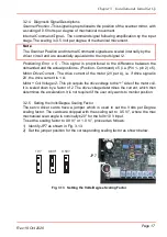
1) Fit a lens post into the bottom of the mounting bracket, then clamp the motor/
mirror assembly to the breadboard.
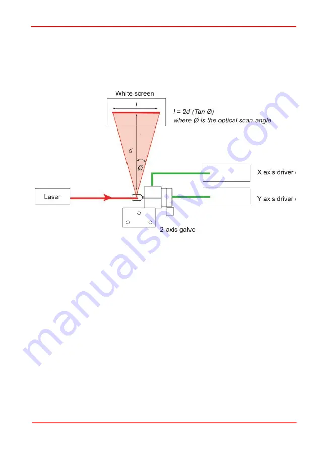
2) Arrange a beam steering system such that a laser beam shines on to the X axis
mirror, at right angles to the mount and is then reflected onto a screen, also at right
angles to the mount..
Typical example: If the optical scan angle Ø = ±40°
l = 2d x Tan 40° (Note. In this case, the mechanical scan angle is ±20°)
Fig. 3.4 Typical Beam Steering System
3.2 Electrical Installation
3.2.1 Choosing A Power Supply
Thorlabs recommends using the GPS011 linear power supply to power the galvo
controller board(s) as this power supply has been specifically designed for this
purpose. The GPS011 can power up to two driver cards under any drive conditions
and is supplied with all the cables required to connect to the driver cards.
However, customers also have the option of using a third-party power supply or
incorporate the boards into their existing system. In this case care must be taken to
ensure that the power supply voltage and current ratings are within the limits
specified.
The drive electronics require a split rail DC supply in the range ±15V to ±18V. The
cards do not require an accurately regulated supply as the boards themselves have
their own regulators. The maximum current drawn by the driver cards will not exceed
1.2 A rms on each rail. In addition to this, for optimum performance the supply should
be able to provide peak currents of up to 5A on either rail.
Summary of Contents for GVS011
Page 40: ...www thorlabs com ...


