Rev 19 Oct 2020
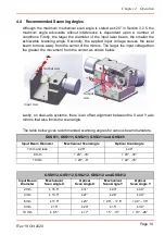
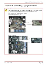
Appendix B Connecting Legacy Driver Units
Page 29
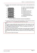
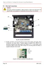
2) Note the serial numbers of the galvo motors and driver boards, then connect the
motors to their associated driver boards. (see Section 3.1.1.)..
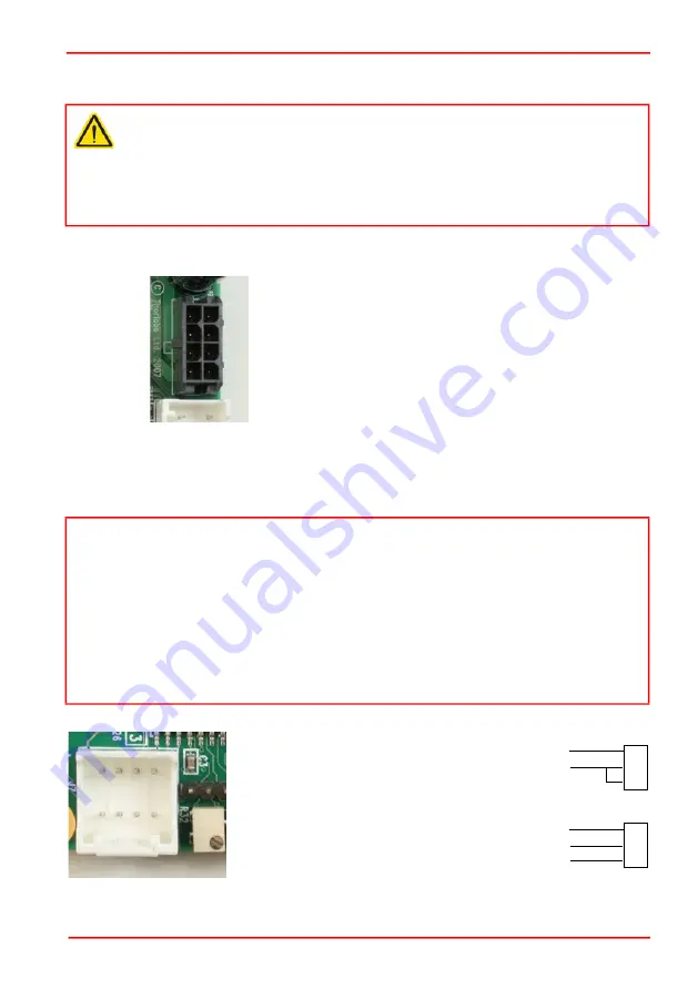
Fig. B.3 J9 Motor Connector Pin Identification.
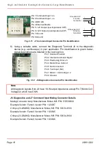
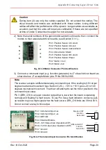
3) Connect a command input (e.g. function generator) to J7 of each driver board as
shown below. J7 accepts Molex pins Pt No 56134-9100.
Fig. B.4 J7 Command Input Connector Pin Identification
Caution
During item (2) use only the cables supplied. Do not extend the cables. The
driver boards and motors are calibrated with these cables. Using different
cables will affect the performance of the system. Longer cables are available as
a custom part but the units will require re-calibration if these are not specified
at time of order. Contact tech support for more details.
Note
The scanner accepts a differential analog command input. If the scaling is 0.5 Volt per
degree mechanical movement (see Section 3.2.5.), -10 V to +10 V gives -20 to +20
degrees mechanical movement. The driver will attempt to set the mirror position to the
command input value.
Pin 3 (DRV_OK) is an open collector output that is low when the board is operating
normally and floating if a fault occurs. To use Pin 3 as a fault indicator, connect a pull-
up resistor to give a high signal when the fault occurs. DRV_OK limits are 30 mA 30 V.
Do not connect a relay to this output.
1
2
3
4
5
6
7
8
Pin 1 Position Sensor A Current
Pin 2 Position Sensor Ground
Pin 3 Position Sensor Cable Shield
Pin 4 Drive Cable Shield
Pin 5 Position Sensor B Current
Pin 6 Position Sensor Power
Pin 7 Motor + Coil
Pin 8 Motor -Coil
1 2 3 4
8 7 6 5
Function
Generator
J7
1
2
7/8
+
-
Function
Generator
J7
1
2
7/8
+
-
Standard O/P
Differential O/P
Earth
Pin 1 Command Input +ve
Pin 2 Command Input -ve
Pin 3 DRV OK
Pin 4 External Enable
Pin 5 -12V Output (low impedence O/P)
Pin 6 +12V Output (low impedence O/P)
Pin 7 Ground
Pin 8 Ground
Summary of Contents for GVS011
Page 40: ...www thorlabs com ...

