background image

Appendix

LEDD3 - FLIM LED Driver User

Manual

Part

VI

Summary of Contents for LEDD3 Series

Page 1: ...2009 Operation Manual Thorlabs Instrumentation LED Illumination System for Fluorescence Lifetime Imaging FLIM LEDD3 ...

Page 2: ...Version Date 1 2 03 03 2009 2009 Thorlabs 2009 Thorlabs ...

Page 3: ...ettings and Configuration 20 2 Remote Application 20 Installation 28 Operating the LEDD3 by the Remote Application 32 3 Changing the LED Part IV Computer Interface 34 34 1 Connecting a Computer 34 2 LEDD3 Utility Software 35 3 Command Reference 35 Command List 35 Description 39 4 Status Reporting Part V Maintenance and Repair 41 41 1 Maintenance 41 2 Firmware Update 41 3 Troubleshooting Part VI Ap...

Page 4: ...ological Background Part VII Listings 54 54 1 List of Acronyms 54 2 List of Figures 56 3 Addresses Part VIII Application Note 58 58 1 Fluorescence Lifetime Imaging FLIM 58 Time Domain FLIM 59 Frequency Domain FLIM Index 1 ...

Page 5: ...ooking forward to hearing from you Thorlabs GmbH This part of the instruction manual contains every specific information on how to handle and use the LEDD3 FLIM LED Driver A general description is followed by explanations of how to operate the unit remotely via the USB connection Attention This manual contains WARNINGS and ATTENTION label in this form to indicate danger for persons or possible dam...

Page 6: ...General Information LEDD3 FLIM LED Driver User Manual Part I ...

Page 7: ...operated correctly Before applying power to your LEDD3 system make sure that the protective conductor of the 3 conductor mains power cord is correctly connected to the protective earth contact of the socket outlet Improper grounding can cause electric shock with damages to your health or even death The LEDD3 must not be operated in explosion endangered environments The LED head control inputs and ...

Page 8: ...st be taken to prevent looking directly at the UV light with unprotected eyes Do not look directly into the UV light or look through the optical system during operation of the device This can be harmful to the eyes even for brief periods due to the high intensity of the UV light If there is the possibility to receive a reflection of the UV light UV light protective glasses have to be used to preve...

Page 9: ...lar installation If this equipment does cause harmful interference to radio or television reception which can be determined by turning the equipment off and on the user is encouraged to try to correct the interference by one or more of the following measures Reorient or relocate the receiving antenna Increase the separation between the equipment and receiver Connect the equipment into an outlet on...

Page 10: ... LEDD3 FLIM LED Driver with LED Head 365nm LEDD3 405 LEDD3 FLIM LED Driver with LED Head 405nm LEDD3 470 LEDD3 FLIM LED Driver with LED Head 470nm LEDD3 630 LEDD3 FLIM LED Driver with LED Head 630nm Other wavelength on request ranging from 365nm up to 940nm Please visit our homepage http www thorlabs com forfurtherinformation ...

Page 11: ...Getting Started LEDD3 FLIM LED Driver User Manual Part II ...

Page 12: ...A 4 1 USB cable 5 1 Operationmanual 6 1 Applications and driver CD 2 2 Preparation 1 Connect LED head cable with socket labeled LED at the back of the main control unit see figure 1 2 Connect power supply cable with main control unit use only the power supply supplied with your LEDD3 unit 3 Plug in power supply Figure 1 Connecting the LED Head GAttentionG Prior to switching on your LEDD3 please ch...

Page 13: ... is immediately ready to use after turning on The rated accuracy is reached however after a warming up period of approximately 10 minutes 2 3 Physical Overview 2 3 1 Operating Elements on the Front Panel Figure 2 Display and Operating Elements on the Front Panel ...

Page 14: ...M LED Driver User Manual 2009 Thorlabs 2 3 2 Operating Elements on the Rear Panel Figure 3 Operating Elements on the Rear Panel 2 3 3 Operating Elements on the LED Head Figure 3a Operating Elements on the LED Head ...

Page 15: ...Operating the LEDD3 LEDD3 FLIM LED Driver User Manual Part III ...

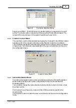
Page 16: ...d Escape functionality The button with LED indicator is used to switch the LED on or off The multi control is used to select the desired menu or to change the settings After switching on the LEDD3 a Welcome screen appears for a few seconds Figure 4 Welcome Screen In case no LED head is connected you will be prompted to switch off the main unit connect the LED head and switch on the device The disp...

Page 17: ...rrent can be changed when the LED is off as well as when it is in operation This allows to increase or reduce the brightness of the LED The current limit is displayed at the bottom of the screen Return to the main menu with the ESC button Figure 6 Constant Current Mode Internal Modulation Mode This mode can be used to apply a sine wave modulation to the LED with a defined frequency The InternalMod...

Page 18: ...h the Ok button or can be canceled with the ESC button Figure 8 Internal Modulation Current Adjustment Figure 9 Internal Modulation Frequency Adjustment Figure 10 Internal Modulation Modulation Depth Adjustment See the chapter TechnicalData for information about cut off frequencies for certain LEDs The following diagram illustrates the definition of current and modulation depth ...

Page 19: ...quivalent to a LED current of 100mA A maximum voltage of 10V can be applied which results in a current of 1000mA Please note The maximum current is limited by the user defined current limit set in the Adjust Limit menu Figure 12 External Control Mode The Modulation Frequency range is 0 to 100kHz and valid for sine wave modulation The last selected operation mode will be saved After switching on th...

Page 20: ... with the Ok button or canceled with the ESC button The LED current limit can be set up to the maximum LED current limit LED Imax which is defined in the EEPROM of the LED head See next section for more information Figure 14 LED Current Limit Setting LED Configuration In case a new LED was installed the LEDs maximum current and frequency need to be configured These values are saved in the EEPROM o...

Page 21: ... can handle this current System Settings Within the system configuration the LCD backlight brightness can be set Select Configuration from the main menu via the multi control knob and press Ok A sub menu appears and the Brightness setting can be accessed by pressing the Ok button The multi control knob is used to change the brightness of the LCD backlight between 0 and 100 Confirm your setting wit...

Page 22: ...erate the LEDD3 FLIM LED Driver via the PC The device has to be connected to the PC by an USB cable 3 2 1 Installation 3 2 1 1 The Installation Menu Before installing the LEDD3 remote application please make sure that no Thorlabs LEDD3 FLIM LED Driver is connected After you inserted the LEDD3 installation CD an autorun menu will appear If autorun is disabled on your system please browsetheinstalla...

Page 23: ...the installation CD You may also download the latest NI VISA runtime engine from the NationalInstruments web site www ni com visa In case you want to use the VISA engine provided on the installation CD select NI VISA Engine An installation wizard will be started If you are running Windows VISTA you might be prompted to change to the elevated mode Please ask your administrator for help when you do ...

Page 24: ... Select I accept the License Agreement s if you do so and press Next Figure 21 License Agreement In the next window please select the features to install To operate the LEDD3 remote application you need at least the USB and the Serial feature see figure 22 Confirm with Next to start installation ...

Page 25: ...Finish to finalize the installation Figure 23 Finalize Installation 3 2 1 3 Installing the Remote Application Select LEDD3 Application software from the installation menu to start the installationwizard IfyouarerunningWindowsVISTA you might be promted to change to the elevated mode as shown in figure 24 Please ask your administrator for help when you do not have administrator privileges ...

Page 26: ...nstallation wizard finished the initialization you will be prompted to specify the installation path Confirm with Next when you selected the installation path of your choice Figure 25 Selecting the Installation Paths During the installation process a separate installation wizard will start to register the device drivers on your system ...

Page 27: ...ess Next and follow this wizard You will be asked two times to Continue anyway the installation Please do so Figure 27 The Windows Logo Test After installation was successful you will see a window containing some information about the installed drivers Press Finish to close the wizard ...

Page 28: ... LEDD3 FLIM LED Driver is automatically copied to the system folder during the installation of the LEDD3 remote application Attention The following procedure will only be necessary for Windows XP 2000 On the first connection of a device the Found New Hardware Wizard will start to install the new device Depending on the configuration of your system you might be asked if you want to connect to Windo...

Page 29: ... Please select No not this time and click Next to continue Figure 30 The Found New Hardware Wizard Select Installthesoftwareautomatically andclick Next tocontinue Figure 31 Choosing the Installation Mode Finalize the installation by clicking Finish ...

Page 30: ... Every setting made will automatically be used by the device The parameters are updated synchronizedonceeverysecond 3 2 2 1 Connecting a Device Please connect the LEDD3 to your PC with the shipped USB cable The USB socket labeled USB at the back of the main control After starting the application the following window is displayed Figure 33 The Start Screen Use the green button or the menu option Co...

Page 31: ...either change the value directly by typing into the numeric control or use the small arrows The maximum value depends on the user current limit which is set in theconfigurationmenu Figure 35 Constant Current Mode 3 2 2 3 Internal Modulation Mode The internal modulation mode can be selected by pressing the Internal Modulation Mode button seefigure36 orthecorrespondingmenuentry Mode Internal Modulat...

Page 32: ...e corresponding menu entry Mode External Control Mode This screen is for information purposes only and offers no user inputs In this mode the LED can only be controlled via the BNC connector at the rear panel of the LEDD3 The applied voltage corresponds to the LED current 1V is equivalent to a LED current of 100mA A maximum voltage of 10V can be applied which will result in a current of 1A Figure ...

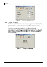
Page 33: ...LEDs maximum current limit stored in the LED head Figure 38 User Limit Figure 39 User Limit Dialog 3 2 2 6 Configuring a new LED The LEDD3 FLIM LED Driver offers the possibility to operate a LED of your choice Use the menu Configuration LED Configuration to set the new LEDs maximum currentandfrequency Figure 40 LED Configuration Menu ...

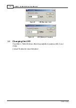
Page 34: ... User Manual 2009 Thorlabs Figure 41 LED Maximum Limit Figure 42 LED Maximum Frequency 3 3 Changing the LED The LEDD3 FLIM LED Driver offers the possibility to operate a LED of your choice Contact Thorlabs for more information ...

Page 35: ...Computer Interface LEDD3 FLIM LED Driver User Manual Part IV ...

Page 36: ...with the instrument and install the LEDD3 drivers When the following message appears after the installation you have to install NI VISA from the distribution CD or fromtheNationalInstrumentswebsite too Figure 43 No VISA Engine installed After successfully installing the software connect the LEDD3 to a USB port of your PC The PC will find sequentially a LEDD3 and a DFU device Please follow the inst...

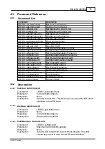
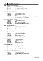
Page 37: ...pth GetInternalModulationDepth LEDD3_setConstCurrent SetConstantCurrent LEDD3_getConstCurrent GetConstantCurrent LEDD3_setDispBright Set Display Brightness LEDD3_getDispBright Get Display Brightness LEDD3_getStatusRegister Get Status Register LEDD3_errorMessage Error Message LEDD3_identificationQuery IdentificationQuery LEDD3_revisionQuery RevisionQuery 4 3 2 Description 4 3 2 1 Set User Limit Cur...

Page 38: ...mfrequencyinMHz Description ReturnstheLEDsmaximumfrequency 4 3 2 7 Set Operation Mode Command LEDD3_setOperationMode Parameter Operation Mode Response None Description Sets the operation mode 4 3 2 8 Get Operation Mode Command LEDD3_getOperationMode Parameter None Response Actual operation mode Description Returnstheoperationmode 4 3 2 9 Set LED OnOff Command LEDD3_setLedOnOff Parameter LED output...

Page 39: ...ription Returnstheinternalmodulationfrequency 4 3 2 15 Set Internal Modulation Depth Command LEDD3_setModuDepth Parameter Modulation depth in percent Response None Description Sets the internal modulation depth in percent 4 3 2 16 Get Internal Modulation Depth Command LEDD3_getModuDepth Parameter None Response Modulation depth in percent Description Returnstheinternalmodulationdepthinpercent 4 3 2...

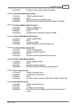
Page 40: ...atus register Refer to chapter StatusReporting 4 3 2 22 Error Message Command LEDD3_errorMessage Parameter Error code Response User readable message string Description Thisfunctiontakestheerrorcodereturnedbytheinstrument driver functions interprets it and returns it as a user readable string 4 3 2 23 Identification Query Command LEDD3_identificationQuery Parameter None Response Manufacturername De...

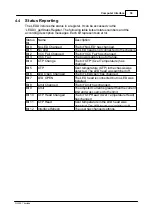
Page 41: ...C Fail The power supply is out of range Bit 4 OTP Change The bit OTP Over Temperature has changed Bit 5 OTP Over temperature OTP in the chassis was detected The LED head was switched off Bit 6 LED Open Changed The bit LED Open has changed Bit 7 LED OPEN The LED head is connected but no LED was installed Bit 8 Limit Changed The bit Limit has changed Bit 9 Limit Theadjustedcurrentisgreaterthanthecur...

Page 42: ...Maintenance and Repair LEDD3 FLIM LED Driver User Manual Part V ...

Page 43: ... hex Both files have to be in the same directory Connect the LEDD3 with a USB cable to your computer Check the COM port of the LEDD3 It has to be COM1 COM2 COM3 or COM4 If not please change the COM port to one of the listed COM ports Before you switch on the LEDD3 press the LED button and keep it pressed while you switch on the device The LEDD3 shows LEDD3 BOOTLOADER in its display Start the batch...

Page 44: ...ed properly to the LEDD3 Check the low voltage line of the power supply LED cannot be switched on Isonofthethreeoperationmodes ConstantCurrent InternalModulationor ExternalControl selected An operation mode can be selected from the main menu using the multi function knob and pressing the Ok button ...

Page 45: ...Appendix LEDD3 FLIM LED Driver User Manual Part VI ...

Page 46: ...s GmbH warrants the hard and software determined by Thorlabs GmbH for this unit to operate fault free provided that they are handled according to our requirements However Thorlabs GmbH does not warrant a faulty free and uninterrupted operation of the unit of the soft or firmware for special applications nor this instruction manual to be error free Thorlabs GmbH is not liable for consequentialdamag...

Page 47: ...t Interruptions and Voltage Variations Immunity Performance Criterion A C 6 FCC EMC Compliance Emissions comply with the Class B Limits of FCC Code of Federal Regulations 47 Part 15 Subpart B 1 3 EC Declaration of Conformity Low Voltage Compliance was demonstrated to the following specification as listed in the Official Journal of the European Communities Low Voltage Directive 73 23 EEC amended by...

Page 48: ...ions which exceed the levels required by these standards may occur when this equipment is connected to a test object 5 MOD IN port capped at IEC 61000 4 3 test 6 Performance Criterion C was reached at additional test levels according to EN 61326 1 2006 table 2 ...

Page 49: ...mm Dimensions W x H x D with operatingelements 160 x 80 x 168 mm 1 non condensing 6 3 2 Technical Data All technical data are valid at 23 5 C and 45 15 rel humidity LED Current Range 0 1000mA ModulationFrequencyRange InternalModulationModeonly 10 100MHz Modulation InternalModulationModeonly Sine Wave ModulationDepth 1 InternalModulationModeonly 0 100 TriggerOutput InternalModulationModeonly Sine W...

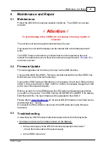
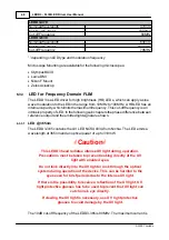
Page 50: ...ifference between reference output and the emitted light signal are shown 6 3 3 1 LED 365nm The LEDD3 365 contains the UV LED NCSU033A from Nichia The LED emits a wavelength at 365nm and an optical power of up to 310mW GCautionG This LEDD3 head radiates intense UV light during operation Precautions must be taken to prevent looking directly at the UV light with unaided eyes Do not look directly int...

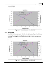
Page 51: ...3 365 6 3 3 2 LED 405nm The LEDD3 405 contains the UV LED LZ1 00UA05 from LedEngin The LED emits a wavelength at 405nm and an optical power of up to 1000mW The 10dB cut off frequency of the LEDD3 405 is 95MHz The maximum current is 1000mA Figure 45 Phase Difference of LEDD3 405 ...

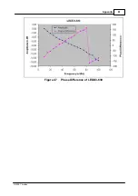
Page 52: ...cal power of up to 60lm The 10dB cut off frequency of the LEDD3 470 is 80MHz The maximum current is 1000mA Figure 46 Phase Difference of LEDD3 470 6 3 3 4 LED 630nm The LEDD3 630 contains the red LED LZ1 00R105 from LedEngin The LED emits a wavelength at 630nm and an optical power of up to 100lm The 10dB cut off frequency of the LEDD3 630 is 70MHz The maximum current is 1000mA ...

Page 53: ...51 Appendix 2009 Thorlabs Figure 47 Phase Difference of LEDD3 630 ...

Page 54: ...ch as pure OEM products that means assemblies to be built into a unit by the user e g OEM laser driver cards components mechanics and optics left over parts of units disassembled by the user PCB s housings etc If you wish to return a Thorlabs unit for waste recovery please contact Thorlabs or yournearestdealerforfurtherinformation 6 4 1 Waste Treatment on your own Responsibility If you do not retu...

Page 55: ...Listings LEDD3 FLIM LED Driver User Manual Part VII ...

Page 56: ...Elements on the LED Head Figure 4 Welcome Screen Figure 5 MainMenu Figure 6 ConstantCurrentMode Figure 7 InternalModulationMode Figure 6 InternalModulation CurrentAdjustment Figure 9 InternalModulation FrequencyAdjustment Figure 10 InternalModulation ModulationDepthAdjustment Figure 11 Definition of the Parameter Current and Modulation Depth Figure 12 ExternalControlMode Figure 13 MainMenu Figure ...

Page 57: ...og Figure 35 ConstantCurrentMode Figure 36 TheInternalModulationMode Figure 37 TheExternalControlMode Figure 38 User Limit Figure 39 User Limit Dialog Figure 40 LED Configuration Menu Figure 41 LED Maximum Limit Figure 42 LEDMaximumFrequency Figure 43 No VISA Engine installed Figure 44 Phase Difference of LEDD3 365 Figure 45 Phase Difference of LEDD3 405 Figure 46 Phase Difference of LEDD3 470 Fig...

Page 58: ...n NJ 07860 USA Sales and Support Phone 1 973 579 7227 Fax 1 973 300 3600 Email sales thorlabs com Email techsupport thorlabs com Web www thorlabs com Japan Thorlabs Inc 1th Floor Higashi Ikebukuro Q Building 2 32 2 HigashiIkebukuro Toshima ku Tokyo 170 0013 Japan Sales and Support Phone 81 3 5979 8889 Fax 81 3 5979 7285 Email sales thorlabs jp Web www thorlabs jp Our company is also represented by...

Page 59: ...Application Note LEDD3 FLIM LED Driver User Manual Part VIII ...

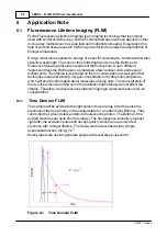
Page 60: ...n the ion concentration as well as further factorslikemolecularbinding oxygenconcentrationorhydrophobicproperties which will provide information about molecules of living cells The concentration of the dye the dimension of the cell or the excitation light intensity will not affect the lifetime Therefore the fluorescence lifetime imaging is a precise measure for ion concentration 8 1 1 Time Domain ...

Page 61: ...d modulates the fluorescence Due to the lifetime of the electrons in the excited state there will be a phase shift between the excitation signal and the fluorescenceresponse Furthermore theintensitytotheexcitationandfluorescence sine waves will be modulated The lifetime can be calculated from the modulation ratio of the intensity Hence the FLIM in the frequency domain provides 2 values for thelife...

Page 62: ......
Reviews: