


LFE1220-US, -EU, and -UK Laminar Flow Enclosures
Chapter 3: Installation
Page 12
ETN055682-D02
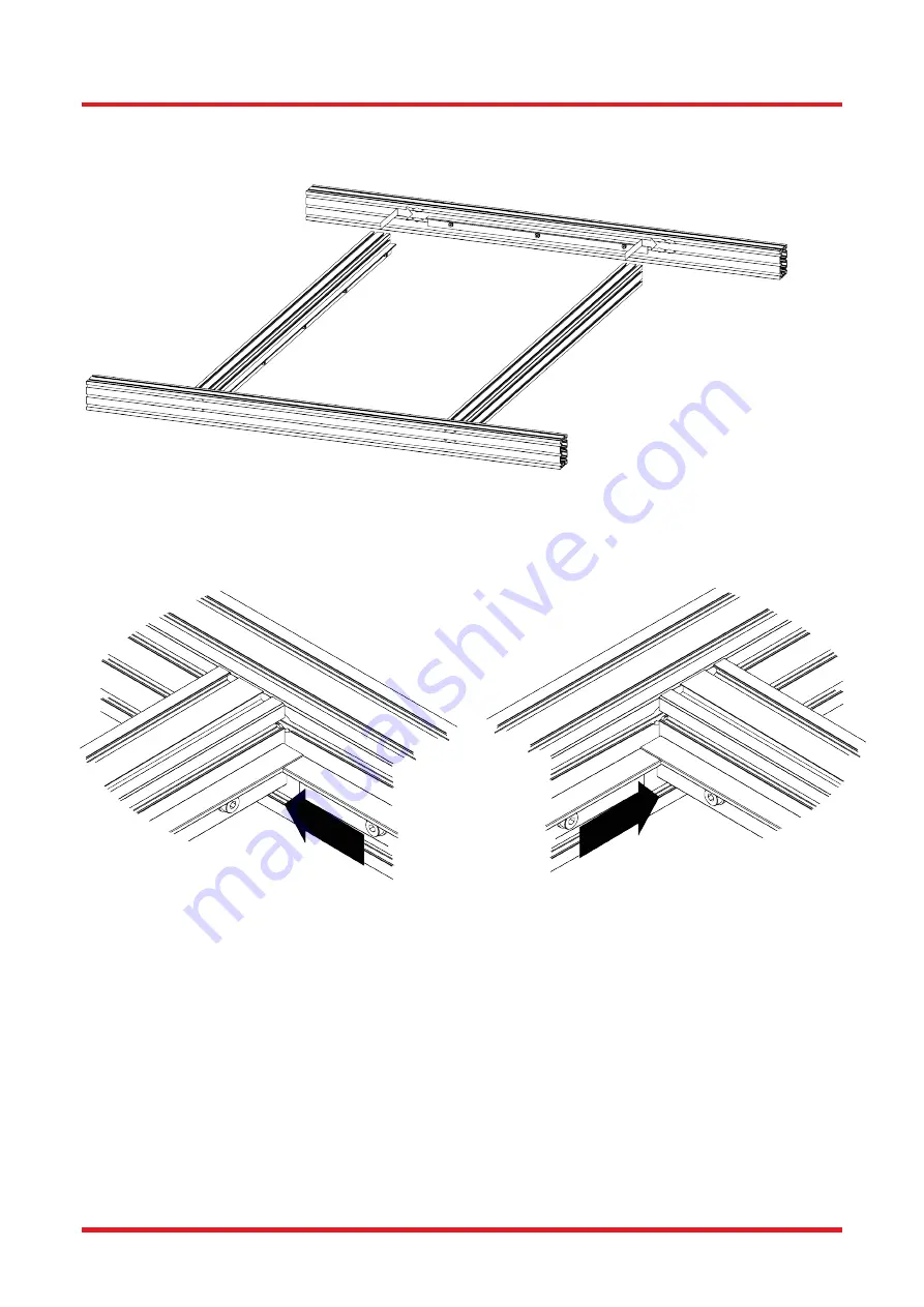
8. Repeat step 3 to loosen the flange on the other Lateral Filter Support. Move the flange to the left by approx.
12.5 mm [0.5"]. This will allow the screws in the ends of both longitudinal filter supports to be inserted via the T-
slot recesses. Slide across and tighten the screws as per step 7.
Figure 8 Assembly of Longitudinal and Lateral Filter Supports – Step 8
9. Re-tighten the filter flanges on the lateral supports, making sure the flange faces are all flush and parallel to each
other
.
Figure 9 Assembly of Longitudinal and Lateral Filter Supports – Step 9
10. Cut the foam tape (L) into two 600 mm [23.6"] lengths and two 1180 mm [46.5"] lengths.
Summary of Contents for LFE1220-EU
Page 60: ...www thorlabs com ...


