LFE1220-US, -EU, and -UK Laminar Flow Enclosures
Chapter 3: Installation
Rev A August 2020
Page 17
3.5. Upright Frame Assembly
3.5.1. Required Parts:
Code
Description
Qty
D
Short Top Cross Member
2
E
Frame Upright
4
F
Long Lower Cross Member
2
G
Short Lower Cross Member
2
AI
Adjustable Foot
4
Tools Required
AL
4 mm T-handle hex driver
AO
Assembly tool
3.5.2. 1
st
Long Side Assembly
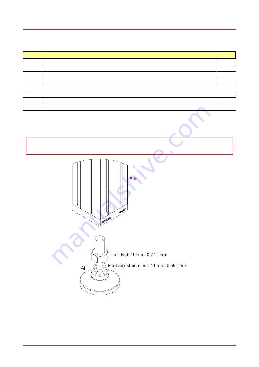
17. Fit the adjustable foot (AI) into the plate at the bottom of each Frame Upright (E
). The adjustable foot can be
adjusted using standard 19mm [0.74"] and 14 mm [0.55"] spanners (not provided).
IMPORTANT
It would be beneficial to set the desired adjustable foot height during this step. Adjusting the foot height will be more
difficult once the frame assembly is complete.
Figure 15 Fitting the Adjustable Feet
18. Set the spacing of the low profile screws (as per step 2) in the end faces of all the construction rails needed for
the Upright Frame Assembly: 2x Short Top Cross Members (D
), 2x Long Lower Cross Members (F
) and 2x
Short Lower Cross Members (G
).
Summary of Contents for LFE1220-EU
Page 60: ...www thorlabs com ...


