background image

LFE1220-US, -EU, and -UK Laminar Flow Enclosures


Chapter 3: Installation


Rev A August 2020 

Page 43


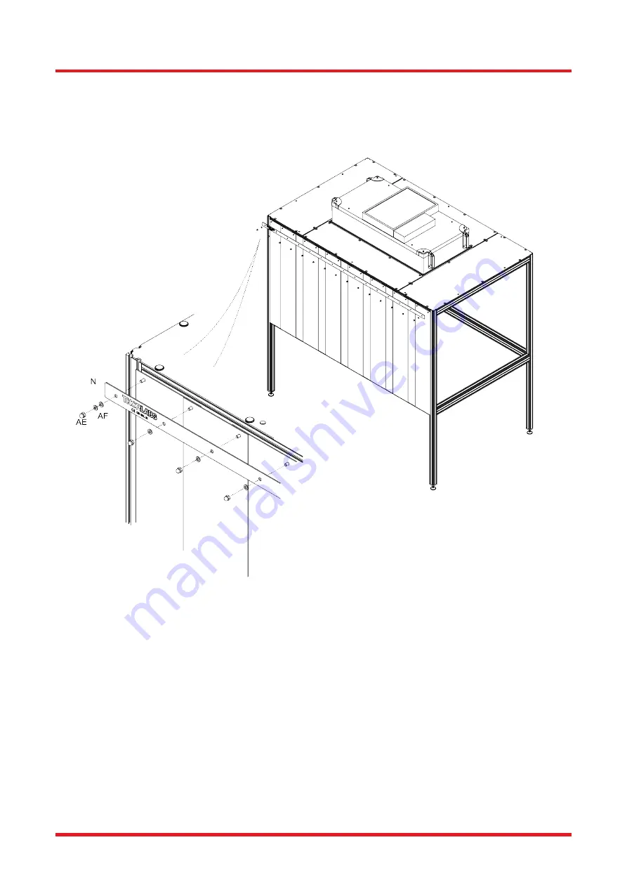
46.  Fit the Curtain Clamp – Long (N) over the protruding Hammer Head Screws, and on each Hammer Head Screw 

fit an M6 Washer (AF) and M6 Domed Nut (AE). The 2 end-most Hammer Head Screws will require 2x M6 
Washers.  
Initially, Domed Nuts can be tightened by hand to secure the Curtain Clamp. To fully tighten the Domed Nuts, use 
a standard 10mm [0.39"] spanner.  


 Figure 45  Fitting the Curtain Clamp 


47.  Repeat steps 41 to 46 for the other long side of the enclosure.  


Summary of Contents for LFE1220-EU

Page 1: ...LFE1220 US EU and UK Laminar Flow Enclosures LFE1220 US LFE1220 EU and LFE1220 UK Laminar Flow Enclosures Installation Manual Original Instructions ...

Page 2: ...Roof Fitting 24 3 6 1 Required Parts 24 3 6 2 Roof Panel fitting 24 3 6 3 Roof Fitting 28 3 7 Fitting the HEPA Fan Filter Unit FFU 31 3 7 1 Required Parts 31 3 7 2 Fitting the HEPA FFU 31 3 8 Lighting 34 3 8 1 Required Parts 34 3 8 2 LED Light Strip Attachment 36 3 9 Fitting Curtains 39 3 9 1 Required Parts 39 3 9 2 Long Side Curtain Assembly 39 3 9 3 Short Side Curtain Assembly 44 3 10 Attach Cur...

Page 3: ...LFE1220 US EU and UK Laminar Flow Enclosures 7 1 Declarations of Compliance 54 7 1 1 For Customers in Europe 54 7 1 2 For Customers In The USA 55 Chapter 8 Thorlabs Worldwide Contacts 56 ...

Page 4: ... in the reduction of airflow turbulence The HEPA filter units shipped with the US and EC enclosures require a voltage of 115 V and 230 V respectively Caution The LFE system has been designed to fit a 1 2 m x 2 0 m 4 x 6 Nexus optical table Other table makes and sizes may not be compatible Note Intended use of the Air Quality Monitor The Air Quality Monitor included in the LFE1220 system is intende...

Page 5: ...stallation and must conform to any applicable local standards The unit must be installed only by suitably trained and qualified personnel who understand the hazards associated with using high voltages and the steps necessary to minimize the risk of electrical shock Warning If this equipment is used in a manner not specified by the manufacturer the protection provided by the equipment may be impair...

Page 6: ...o ensure optimal Fan Filter Unit performance Caution Ensure that proper airflow is maintained to the Fan Filter Unit Insufficient air flow will cause overheating and premature failure 3 2 Environmental Conditions Warning Operation outside the following environmental limits may adversely affect operator safety Location Indoor use only Maximum altitude 2000 m Temperature range 15 C to 40 C Maximum H...

Page 7: ... the various parts until they are required Enclosure Frame Code Description Qty Image A Longitudinal Filter Support Cross section 50 x 50 mm Length 1215 mm 2 B Lateral Filter Support Cross section 50 x 75 mm Length 1230 mm 2 C Long Top Cross Member Cross section 50 x 75 mm Length 2100 mm 2 D Short Top Cross Member Cross section 50 x 75 mm Length 1230 mm 2 E Frame Uprights Cross section 50 x 50 mm ...

Page 8: ...sure Frame Continued Code Description Qty Image J Roof Panel Outer 2 K HEPA FFU Fan Filter Unit 1 L Foam Tape inside HEPA FFU Box 1 M Curtain Clamp Short 2 N Curtain Clamp Long 2 O Curtain Bar 1 P XE25S2 Slot Cover Profile 3 Q Lifting handle LH 2 R Lifting handle RH 2 S AQM001 Air Quality Monitor 1 ...

Page 9: ...Long 4 AB 20 x Cap Screw 4 AC M6 x 1 0 Hammerhead Screw 12 7mm Long XE25HM6 50 AD M6 Square Nut 4 AE M6 Domed Nut 50 AF M6 Washer 66 AG Barrel Plug 22 AH Push Rivet 42 AI Adjustable Foot 4 AJ Curtain bar bracket 2 AK M8 x 1 25 Cap Screw 14mm Long 2 AL 4mm T handle hex driver 2 AM 6mm hex key 1 AN 3 16 hex key 1 AO Assembly tool 2 AP Cable Gland 1 2 extra components included ...

Page 10: ...pter 3 Installation Rev A August 2020 Page 7 Lighting Components Tube Code Description Qty Image BA XE25T1 M Drop in Nut 3 BB M6 x 1 0 Button Screw 6mm Long 3 BC LED mounting clip 3 BD LED light strip 1 BE LED switch extension 1 BF 12V Power Supply 1 ...

Page 11: ... Code Description Qty A Longitudinal Filter Support 2 B Lateral Filter Support 2 C Long Top Cross Member 2 L Foam Tape 1 Tools Required AL 4 mm T handle hex driver AO Assembly tool 3 4 2 Inner Frame Assembly 1 Take 2x Longitudinal Filter Supports A and 2x Lateral Filter Supports B Figure 1 Identification of Longitudinal and Lateral Filter Supports ...

Page 12: ...An assembly tool AO has been provided for this purpose To set the spacing loosen the screws from their pre installed position using the 4mm T handle hex driver AL insert the assembly tool AO under the screw heads tighten the screws against the assembly tool then back off 1 4 turn to release the assembly tool For this step set the spacing of the low profile screws in both ends of the Longitudinal S...

Page 13: ...slot recesses of the Lateral Filter Support and slide across approx 12 5mm 0 5 to align the screws with the through holes Figure 4 Assembly of Longitudinal and Lateral Filter Supports Step 4 5 Slide the loose flange across to meet the flange fixed to the Longitudinal Filter Support Figure 5 Assembly of Longitudinal and Lateral Filter Supports Step 5 ...

Page 14: ... the T slots clamping the parts together To access the screw heads for tightening through holes have been drilled in the construction rails and the provided 4mm T handle hex driver AL is passed through the holes To give the correct tightness the screws should be turned between 1 rotation For this step Using the 4mm T handle hex driver AL tighten the 8 screws Ensure the top faces of the constructio...

Page 15: ...longitudinal filter supports to be inserted via the T slot recesses Slide across and tighten the screws as per step 7 Figure 8 Assembly of Longitudinal and Lateral Filter Supports Step 8 9 Re tighten the filter flanges on the lateral supports making sure the flange faces are all flush and parallel to each other Figure 9 Assembly of Longitudinal and Lateral Filter Supports Step 9 10 Cut the foam ta...

Page 16: ...ugust 2020 Page 13 11 Stick the lengths of sealing tape to the top of the flanges by removing the adhesive backing strip Stick the 600 mm lengths first then the 1180 mm lengths Set the assembly to one side Figure 10 Assembly of Longitudinal and Lateral Filter Supports Step 11 ...

Page 17: ... 4 3 Roof Frame Assembly 12 Set the spacing of the low profile screws in both ends of each Lateral Filter Support as per step 2 Figure 11 Roof Frame Assembly Step 12 13 Set the spacing of the low profile screws in both ends of each Long Top Cross Member C Figure 12 Roof Frame Assembly Step 13 ...

Page 18: ...5 14 It is recommended that 2 people perform this step Insert and slide the inner frame from step 11 into the Long Top Cross Member Tighten the screws using the T handle hex driver as per step 7 ensuring the upper faces of the construction rails are flush Figure 13 Roof Frame Assembly Step 14 ...

Page 19: ... Chapter 3 Installation Page 16 ETN055682 D02 15 It is recommended that 2 people perform this step Repeat step 14 to attach the remaining Long Top Cross Member Figure 14 Roof Frame Assembly Step 15 16 Put finished Roof Frame Assembly to one side ...

Page 20: ...I into the plate at the bottom of each Frame Upright E The adjustable foot can be adjusted using standard 19mm 0 74 and 14 mm 0 55 spanners not provided IMPORTANT It would be beneficial to set the desired adjustable foot height during this step Adjusting the foot height will be more difficult once the frame assembly is complete Figure 15 Fitting the Adjustable Feet 18 Set the spacing of the low pr...

Page 21: ...TN055682 D02 19 It is recommended that 2 people perform this step Select two Frame Uprights E Ensure the T slot recesses are on the 2 inward faces and the positioning screws are facing inwards towards each other as shown in the picture Figure 16 First Long Side Assembly Step 19 ...

Page 22: ... T slot recesses and tighten the screws as per step 7 Warning Risk of Finger Trap Depending on the size of the enclosed optical table there may be a risk of trapping and or injuring fingers in the gap between the table and the lower cross member IMPORTANT Ensure that warning labels on the lower cross members are displayed on the top face of the lower cross member with the triangle pointing inwards...

Page 23: ...mbly 21 It is recommended that 2 people perform this step Select a Frame Upright E and a Short Lower Cross Member G Ensure the T slot recesses and positioning screw are aligned as shown Similarly to step 20 fit the Short Lower Cross Member into the uprights and tighten the screws Figure 18 First Short Side Assembly ...

Page 24: ... Lower Cross Member F similarly to step It is recommended that 2 people perform this step Select a Frame Upright E and a Short Lower Cross Member G Ensure the T slot recesses and positioning screw are aligned as shown Similarly to step 20 fit the Short Lower Cross Member into the uprights and tighten the screws 20 making sure the T slot recesses and position screw are aligned correctly Figure 19 S...

Page 25: ... 2nd Short Side Assembly 23 It is recommended that 2 people perform this step Fit the remaining Short Lower Cross Member G into the assembly and tighten the screws The frame will flex sufficiently for the screw heads to be inserted through the T slot recesses Figure 20 Second Short Side Assembly ...

Page 26: ...on Rev A August 2020 Page 23 24 It is recommended that 2 people perform this step Insert the 2x Short Top Cross Members D from the top of the uprights until the screw heads align with the through holes Tighten the screws Figure 21 Fitting the Short Top Cross Members ...

Page 27: ... 2 Roof Panel fitting 25 Peel back the protective plastic film from Roof Panels I and J just enough so that the fixing holes can be accessed IMPORTANT The Roof Panels I and J are protected by plastic film on both sides For maximum protection during the assembly of the enclosure it is recommended to only partially remove the film enough so that the fixing holes can be accessed as indicated by the d...

Page 28: ... have 1 glossy and 1 matte side The panels can be assembled with either finish on the inside of the frame orientate your parts according to the desired finish The smaller holes 7 mm 0 28 in the panel periphery should align with the T slots in the construction rails and the larger holes 10 1 mm 0 40 should align with through holes in the frame Figure 23 Locating the Roof Panels ...

Page 29: ...rough the smaller 7 mm holes The alignment mark should be parallel to the edge that the push rivet is located in as indicated in the image below The push rivets have 2 parts 1 the lower part inserts into the hole and the 2 the top part is then pushed in which expands the rivet and locks it in place Figure 24 Inserting the Rivets ...

Page 30: ...LFE1220 US EU and UK Laminar Flow Enclosures Chapter 3 Installation Rev A August 2020 Page 27 28 Fit 6x barrel plugs AG push fit Figure 25 Fitting the Barrel Plugs ...

Page 31: ...g screws these will hold the roof in place Then tighten the screws as per step 7 Warning Due to the geometry and weight of the roof panel four people are required to perform this step Fitting the roof will require the use of stepladders or stepstools These must be postioned as close to the frame as possible to prevent overeaching DO NOT stand on the roof The maximum load per roof panel is a 40kg d...

Page 32: ...S EU and UK Laminar Flow Enclosures Chapter 3 Installation Rev A August 2020 Page 29 30 Fit the remaining 4x barrel plugs and 6x push rivets in the roof panels Figure 27 Fitting the Barrel Plugs and Push Rivets ...

Page 33: ... Enclosures Chapter 3 Installation Page 30 ETN055682 D02 31 Fit qty 10 AG barrel plugs into the corresponding holes on the underside of the top cross members Figure 28 Fitting the Barrel Plugs to the Underside of the Top Cross Members ...

Page 34: ...le gland AP has been provided for installation in the electrical entrance Risk of Electrical Shock Installation work and electrical wiring must be done by qualified person s in accordance with all applicable codes and standards Cables for wiring the Filter Unit are not supplied These must be provided by the person responsible for installation and must conform to any applicable local standards The ...

Page 35: ...hten the Cap Screws Figure 29 Fitting the Lifting Handles 34 Set the FFU to a desired speed Please refer to the MAC 10 Original VE5 FAN FILTER MODULE INSTALLATION AND SERVICE MANUAL for more guidance on the speed options Figure 30 FFU Speed Control IMPORTANT The speed switch will be difficult to access once the FFU has already been mounted on top of the enclosure For ease of operation select your ...

Page 36: ...assembled in step 3 4 2 Avoid sliding it into place to prevent damage to the foam tape Warning You should ensure that the installers are capable of lifting and supporting the weight of the FFU prior to lifting it onto the top of the frame Lifting the FFU will require the use of 2 stepladders or stepstools These must be postioned as close to the frame as possible to prevent overeaching Figure 31 In...

Page 37: ...rew 6mm Long 3 BC LED mounting clip 3 BD LED light strip 1 BE LED switch extension 1 BF 12V Power Supply 1 P XE25S2 Slot Cover Profile 3 Tools Required AL 4mm T handle hex driver The T slots of the construction rails allow flexibility in the placement of the LED light strip Some recommended placement options for the light strip are shown below Figure 32 Recommended Lighting Placement Options ...

Page 38: ...sures Chapter 3 Installation Rev A August 2020 Page 35 The cable routing will be determined by the chosen light position An example of the light strip position and corresponding routing of cable is shown below Figure 33 Cable Routing Example ...

Page 39: ... the slot that corresponds to your chosen position The nuts should be spaced approx 350 mm 13 8 apart Figure 34 Inserting the Drop in Nuts 37 Using qty 3 LED mounting clips BC and qty 3 M6x6 Button Screws BB secure the light clips to the XE25T1 M Drop in Nuts inserted above A 4mm T handle hex driver is supplied to tighten the screws Figure 35 Fitting the Light Clips ...

Page 40: ...e LED light strip BD by pressing into the 3 clips Figure 36 Fitting the Light Strip 39 The LED switch extension BE has been provided to enable the switching of the lights from a more accessible position This connects between the LED light strip and 12V Power Supply BF Figure 37 LED Switch Extension Cable ...

Page 41: ...side the T slots of the construction rail The provided XE25S2 Slot Cover Profiles P can be used to hide and secure the cables once routed The Slot Cover can be easily cut to the desired length and pushed into place as shown in the example image below Figure 38 Cable Routing Inside the T Slots and Slot Cover Profile Use ...

Page 42: ...r Head Screw 48 AE M6 Domed Nut 48 AF M6 Washer 56 3 9 2 Long Side Curtain Assembly 41 Insert the first Hammer Head Screw AC into the centre slot Have the long edge of the hammerhead parallel to the slot and insert then rotate clockwise to prevent it from falling out The gap between the frame upright and the edge of Hammer Head Screw should be approx 6 5mm 0 26 Figure 39 Inserting a Hammer Head Sc...

Page 43: ...x 150mm 5 9 from the first Place one Curtain Strip H onto these two Hammer Head Screws Figure 40 Inserting a Second Hammer Head Screw and Hanging a Curtain Strip 43 Insert 2x additional Hammer Head Screws and 1x additional Curtain Strip with approx 150mm spacing between each Hammer Head Screw Figure 41 Hanging a Second Curtain Strip ...

Page 44: ...n Strip on top of the first two assembled to cover the gap Figure 42 Hanging the Next Curtain Strip 45 Repeat steps 43 and 44 until the whole side is covered with curtains 14 strips in total This overlapping pattern is important to help with access through the curtains Figure 43 Hanging the Remaining Curtain Strips ...

Page 45: ...LFE1220 US EU and UK Laminar Flow Enclosures Chapter 3 Installation Page 42 ETN055682 D02 Figure 44 Completed Curtain Assembly On One Long Side ...

Page 46: ...d on each Hammer Head Screw fit an M6 Washer AF and M6 Domed Nut AE The 2 end most Hammer Head Screws will require 2x M6 Washers Initially Domed Nuts can be tightened by hand to secure the Curtain Clamp To fully tighten the Domed Nuts use a standard 10mm 0 39 spanner Figure 45 Fitting the Curtain Clamp 47 Repeat steps 41 to 46 for the other long side of the enclosure ...

Page 47: ...6 Inserting a Hammer Head Screw on the Short Side of the Frame 49 Repeat steps 41 to 46 for the short side using 8 Curtain Strips in total and using Curtain Clamp Short M in place of Curtain Clamp Long N Figure 47 Completed Curtain Assembly on the Short Side of the Frame 50 Repeat steps 48 and 49 for the other short side 51 The enclosure is now complete make final adjustments to the feet and lock ...

Page 48: ...Enclosure Warning The Curtain Bar is not a structural member and should not be used to hang anything other than the strip curtains 3 10 1 Required Parts Code Description Qty O Curtain Bar 1 AA M6 x 1 0 Low Profile Channel Screw 10mm Long 4 AD XE25T3 M Square Nut 4 AF M6 Washer 4 AJ Curtain Bar Bracket 2 AK M8 x 14 Cap Screw 2 Tools Required AL 4 mm T handle hex driver AM 6mm hex key 3 10 2 Attachi...

Page 49: ...Installation Page 46 ETN055682 D02 53 Slide the square nuts on the assembled brackets into the outermost T slots Set the bracket to the required height and then tighten using the T handle hex driver AL Figure 49 Fitting the Curtain Bar Brackets to the Frame ...

Page 50: ...low Enclosures Chapter 3 Installation Rev A August 2020 Page 47 54 Attach the Curtain Bar O to the brackets using 2x M8 x 1 25 Cap Screw 14mm Long AK and tighten with 6mm hex key AM Figure 50 Fitting the Curtain Bar to the Brackets ...

Page 51: ...itor 4 1 Box Contents Figure 51 AQM Box Contents 4 2 Installation 1 Loosen the mounting plate T nuts by a couple of turns and align them to the slots in the extrusion Note below the different arrangement for fixing to vertical and horizontal extrusion shown in Figure 52 and Figure 53 Figure 52 Fixing to Vertical Extrusion ...

Page 52: ...uality Monitor Rev A August 2020 Page 49 Figure 53 Fixing to Horizontal Extrusion 2 Place the mounting plate onto the extrusion inserting the T nuts into the slots and tighten the two M4 screws using the supplied 3 mm hex key Figure 54 Fitting the Mounting Plate ...

Page 53: ...ighten the thumbscrew Figure 55 Fitting the USB Cable Head 4 Line up two of the key holes on the back of the AQM with the two protruding screws on the mounting plate Move the AQM onto the mounting plate so that the two protruding screws enter the key slots then push down on the AQM to lock the unit to the mounting plate Figure 56 Fitting the AQM Unit to the Mounting Plate ...

Page 54: ... USB power supply or a computer USB port The unit will turn on and remain on when plugged in 4 3 Function Description The AQM will turn on and remain on when it is connected to a power source It has a single function and operates continuously providing a live representation of the air quality inside your LFE or anywhere else in your lab The LH column shows the particulate matter size in microns µm...

Page 55: ... FILTER MODULE INSTALLATION AND SERVICE MANUAL for more detailed instructions 5 1 1 Removing the HEPA FFU from the Roof 1 To remove the HEPA FFU from the top of the enclosure follow the same process as in step 35 but in reverse 2 Reinstall following the same process as in step 35 5 2 Removing Push Rivets This can be done by lifting the head of the rivet with a flat head screw driver or similar too...

Page 56: ...ail 100 kg Total Weight 150 kg Foot Height Adjustment 11 5 mm HEPA Filter Efficiency 99 95 Internal Dimensions 1230 mm x 2100 mm Compatible Table Size 1 2 m x 2 0 m 4 x 6 Notes 1 To prevent the frame toppling any attached load which acts outside the perimeter of the frame should not create a moment load 800Nm about an axis between any 2 of the feet 2 The maximum load per roof panel is a 40kg distr...

Page 57: ...LFE1220 US EU and UK Laminar Flow Enclosures Chapter 7 Regulatory Page 54 ETN055682 D02 Chapter 7 Regulatory 7 1 Declarations of Compliance 7 1 1 For Customers in Europe ...

Page 58: ...n the equipment is operated in a commercial environment This equipment generates uses and can radiate radio frequency energy and if not installed and used in accordance with the instruction manual may cause harmful interference to radio communications Operation of this equipment in a residential area is likely to cause harmful interference in which case the user will be required to correct the int...

Page 59: ...t wheelie bin logo see right were sold to and are currently owned by a company or institute within the EC and are not dissembled or contaminated Contact Thorlabs for more information Waste treatment is your own responsibility End of life units must be returned to Thorlabs or handed to a company specializing in waste recovery Do not dispose of the unit in a litter bin or at a public waste disposal ...

Page 60: ...www thorlabs com ...

Reviews: