Page 6
22115-D02
MLS203 Series XY Scanning Stage
3.3 Electrical Connections
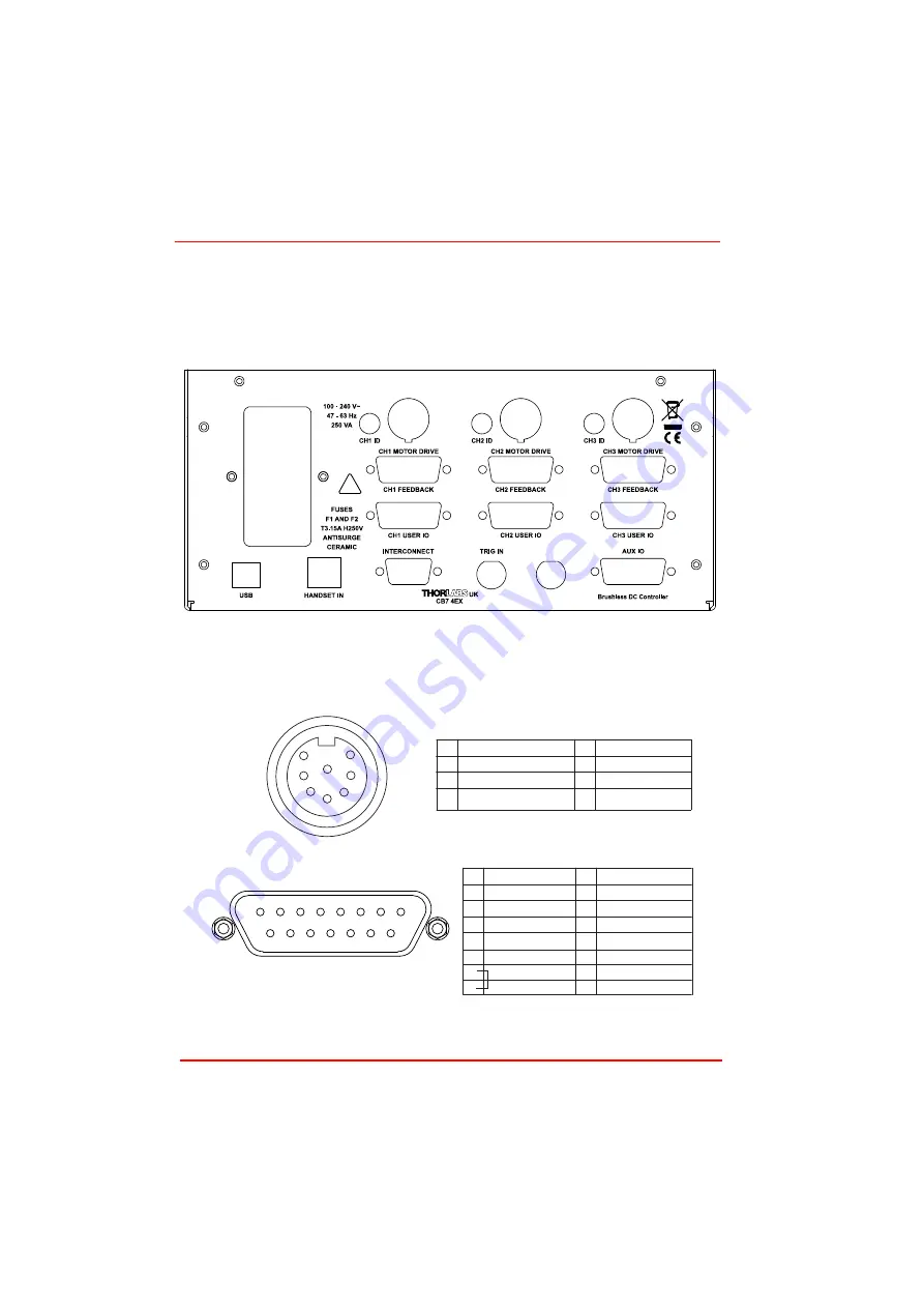
The stage must be driven by a Thorlabs BBD series controller. Connect the motor
leads to the MOTOR DRIVE connectors, and the encoder feedback leads to the
FEEDBACK connectors. Ensure that the motor drive and feedback leads for each
motor are connected to the correct channel.
Fig. 3.3 Electrical connections
Pin out information for the motor drive and encoder feedback connectors on the motor
flying leads is detailed below.
Fig. 3.4 Motor Drive and Feedback Flying Lead Pin Out Details
TRIG OUT
!
1 Motor Phase V
2 GND
3 Thermistor (not used)
4 Motor Phase U
5 Stage ID
6 GND
7 Motor Phase W
8 Enable
1
2 GND
3
4 Enc Index -
5 QB -
6 QA -
7 5 V
8 5 V
9 GND
10 Limit
11 Limit Switch -
12 Enc Index +
13 QB +
14 QA +
15 x
3
5
8
2
6
4
1
7
8
7
6
5
4
3
2
1
15
14
13
12
11
10
9
MOTOR DRIVE
ENCODER FEEDBACK


