GPX3800 and GPX3850 Glass Processors
Chapter 4: Setup
Page 12
TTN047534-D02
Chapter 4
Setup
1.
Unpack PC, monitor and peripherals. Set-up the computer using the included instructions from the
computer manufacturer.
2.
Unpack the glass processor workstation and place it on a workbench. Make sure not to damage any
components of the glass processor during handling of the workstation. Lift the unit using the retractable
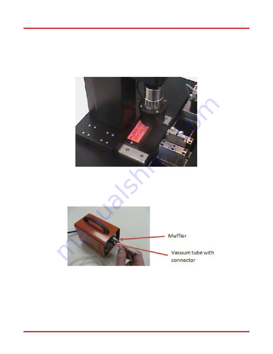
handles only. Remove the transport block marked with the red “PLEASE REMOVE BEFORE USE” label
from the base of the camera tower and store in a secure location for future use.
Transport Blocks Located Near Camera Tower
3.
Connect the external vacuum pump:
4.
Connect the muffler to the top connector of the vacuum pump.
5.
Connect the bottom connector on the vacuum pump, labeled “VAC” with the included tube to the back of
the glass processor
labeled “VACUUM”.
External Vacuum Pump
6.
Connect the camera with the supplied IEEE-1394 Fire Wire cable to the port on the glass processor
labeled “CAMERA” and to the Fire Wire port on the computer. The connector has a directional design so
be sure to orientate the connector correctly. Both the computer and glass processor workstation
MUST
be off during this operation, otherwise damage to the CCD camera can occur.
7.
Connect the serial communication cable (RS-232) to the outlet in the back of the workstation labeled
“SERIAL COMMS” and to the computer’s serial communication port (see instructions from the computer
manufacturer). Tighten the screws on both sides of the cable to secure it in place.


