SensaLink Scene Select Panel SENSALINK SENLSS V2
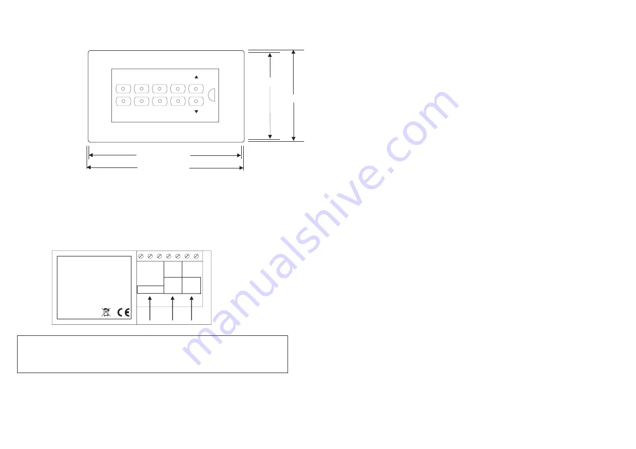
Dimensions
Only suitably qualified personnel should install this equipment
82mm
86mm
144mm Module
146mm Fascia
OFF
ON
1
2
3
4
5
6
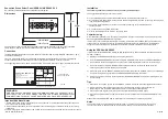
Connection
Important Additional Notes
1. All terminals on this product are provided for final connection. It is not intended that the product be used
as a junction box for looping cables.
2. A means of disconnection must be incorporated in the fixed wiring in accordance with the current wiring
regulations.
3.The dimming signal, while nominally 12V, should not be treated as ELV as its 0V line (D1 above) is close to
Mains Neutral potential.
WARNING
UNDER NO CIRCUMSTANCES SHOULD MAINS POWER (e.g. 200-250V ~) BE
APPLIED TO THE SLK BUS CONNECTIONS OR THE DIGITAL DIMMING OUTPUT
CONNECTIONS. THIS WILL CAUSE DAMAGE AND COULD BE HAZARDOUS.
MAINS INPUTS
DIGITAL
OUTPUT
POLARITY
FREE
POLARITY
FREE
SENSALINK
BUS
L
N
D1 D2
SLK
SLK
230V
~
50Hz.
Power consumption <10W
o
ta 0.. 40 C
Please read instructions prior to installation.
SENSALINK SENLSS V2
DIRECTION OF CABLE INSERTION
VIEW ON REAR OF
MODULE ENCLOSURE
TOP
BOTTOM
The module's enclosure and its supporting frame are designed to attach to the front of any standard
Two-Gang Box, sinking, dry-lining or surface mounting, with a minimum depth of 30mm.
Using the SENSALINK SENLP
It is important that the SENSALINK SENLP be held perpendicular to, and at a distance of between 0.5m and
2m from, the panel.
1) Switch on the SENSALINK SENLP by pressing the red button.
2) Point the SENSALINK SENLP at the panel and press the DOWNLOAD button. The SENSALINK SENLP
will confirm the product's identity and call up the correct menu of parameters and their current settings.
3) Use a combination of UP, DOWN, FORWARD and BACK buttons to navigate the parameter menu,
selecting the options for each shown. (See Tips below.)
4) When complete, aim the SENSALINK SENLP at the panel and press the UPLOAD button. To acknowledge
a successful programming operation, the SENSALINK SENLP displays "DATA OK".
5) After a short period of inactivity (default 5 minutes) the SENSALINK SENLP hibernates retaining the most
recent settings.
Tips
I)
When there are only two options such as ON/OFF, a double click of the OK button toggles between them.
ii)
Where there are multiple options, a double click of the OK button recalls a list of all options for
that parameter. Use the UP, DOWN and OK buttons to select the desired alternative.
iii) Use the OK button to go forward (through the menus) without displaying HELP pages.
iv) Press the UPLOAD button at any time to transfer all current settings from the SENSALINK SENLP to the
panel.
Please refer to the SENSALINK SENLP Instructions for comprehensive commissioning details.
Notes
The panel is capable of recognising group numbers from 1 to 50 and can be programmed to belong
to up to four of these. In addition it can be programmed to belong to up to three Common Groups.
Installation
The following should be carried out only by a suitably qualified person.
The suggested installation procedure is as follows:
a) Fit the double-gang sinking box at the desired location (minimum box depth 30mm).
b) Pull through mains power cable, SensaLink bus cable and digital dimming cable (if required), observing wire
requirements and regulations.
c) Connect to the terminal block at the rear of the module, observing correct terminations and
cautionary notes.
d) Fix module's supporting frame to back box.
e) Clip the fascia plate onto the module's supporting frame.
Commissioning
Once installation is complete, it is necessary to programme the panel's parameters - as with detectors, this is
done using the SENSALINK SENLP Programmer.
In order to work harmoniously with detectors controlling luminaires within the same space as, and linked by
group number to, the luminaires directly controlled by the SensaLink Scene Switch Panel, the Off Delays
configured in the detectors and in the SensaLink Scene Switch Panel should be of the same duration.
W4370B
2
It is imperative that the SensaLink bus is wired with the correct type of cable. Normally it should be 1.5mm
unscreened twisted pair.
Two-core mains-rated cable is recommended for the dimming signal (see Note 3 below). The dimming
control output should be connected only to the control inputs of ballasts - never to a detector.
The supporting frame of the module must be earthed, via its earth terminal, to render the metal fascia safe.


