KATflow 150
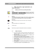
3 Installation
3.7.3
Correct positioning of the sensors
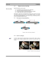
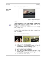
Always mount the transducer pair so that the free front edges of the sensors face
each other.
There is a different engraving on the top of each transducer. The transducers are
mounted correctly if the engravings on the two transducers form an arrow. The
transducer cables should point in opposite directions.
Later, the arrow, in conjunction with the indicated measured value, will help to de-
termine the direction of flow.
The sensor separation distance is automatically calculated by the flowmeter based
on the parameter entries for pipe outside diameter, wall thickness, lining material
and thickness, medium, process temperature, the sensor type and the selected
number of signal passes.
3.7.4
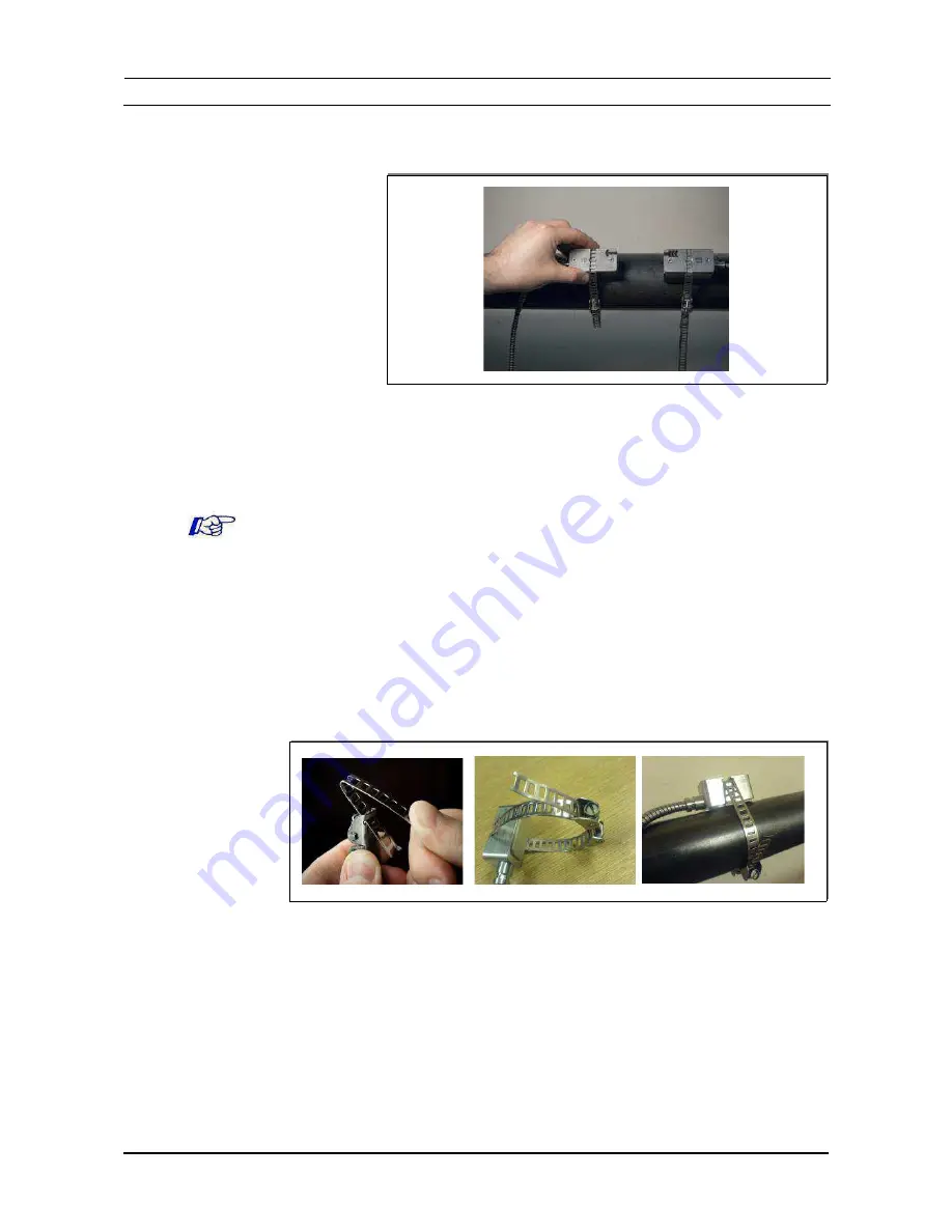
Sensor mounting with tension straps
Cut the tension straps to the appropriate length.
Pull at least 2 cm of the tension strap through the slot in the clamp and
bend the strap back to secure the clamp to the tension strap.
Guide the other end of the tension strap through the groove on top of the
sensor.
Ensure sensors have adequate acoustic couplant.
Place the sensor onto the prepared pipe section.
Hold the clamp on the transducer with one hand and guide the tension
strap around the pipe.
Pull the tension strap and guide the free end through the clamp so that the
clamp hooks engage. Slightly tighten the screw on the clamp.
Mount the second sensor in the same way.
18
Correct sensor
position
Illustration 8: Correct positioning of the sensors
Illustration 9: Metallic mounting straps


