background image

KATflow 150

7 Troubleshooting

7

Troubleshooting

Should there be the need to call customer service, please let us know the following  
details:

Model code

Serial number

SW, HW revision

Error log list

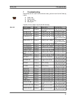
Possible error messages may include the following:

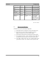
Error message

Group

Description

Error handling

USB INIT FAIL

Hardware

Internal board communic-
ation error

Power on/off, otherwise 
call customer support

NO SERIAL NO.

Hardware

Failed to read from FRAM Call customer support

NO VERSION NO.

Hardware

Failed to read from FRAM Call customer support

PARA READ FAIL

Hardware

Failed to read from FRAM Load defaults, other-

wise call customer sup-
port

PARA WRITE FAIL

Hardware

Failed to write to FRAM

Load defaults, other-
wise call customer sup-
port

VAR READ FAIL

Hardware

Failed to read from FRAM Call customer support

VAR WRITE FAIL

Hardware

Failed to write to FRAM

Call customer support

SYSTEM ERROR

Hardware

Call customer support

VISIBILITY ERR

Hardware

Failed to read from FRAM Call customer support

FRAM LONG WRITE 
ERR

Hardware

Failed to write to FRAM

Call customer support

FRAM READ ERR

Hardware

Failed to read from FRAM Call customer support

RTC ERR

Hardware

Real Time Clock failure

Power on/off, otherwise 
call customer support

EXTMEM ERR

Hardware

Logger memory failure

Power on/off, otherwise 
call customer support

SPI ERR

Hardware

SPI bus failure

Power on/off, otherwise 
call customer support

I2C ERR

Hardware

I2C bus failure

Power on/off, otherwise 
call customer support

MATH ERR

Software

Internal calculation error

Call customer support

STACK ERR

Software

Internal calculation error

Call customer support

ADDR ERR

Software

Internal calculation error

Call customer support

OSC ERR

Software

Internal calculation error

Call customer support

ADC ERR

Software

Internal calculation error

Call customer support

IO ERR

Software

Internal calculation error

Call customer support

TIMING ERR

Software

Internal calculation error

Call customer support

COMM INIT ERR

Hardware

Internal communication 
error

Power on/off, otherwise 
call customer support

COMM START ERR

Hardware

Internal communication 
error

Power on/off, otherwise 
call customer support

COMM HS0 ERR

Hardware

Internal communication 
error

Power on/off, otherwise 
call customer support

40

Error list

Summary of Contents for KATRONIC KATflow 150

Page 1: ...Operating Instructions KATflow 150 Ultrasonic Flowmeter...

Page 2: ...Street Earlsdon Coventry West Midlands CV5 6ET United Kingdom Tel 44 0 2476 714111 Fax 44 0 2476 715446 Internet www katronic co uk E mail mail katronic co uk Operating Instructions KATflow 150 Versio...

Page 3: ...wmeter installation 14 3 6 1 Wall mounting 15 3 6 2 Electrical connections 16 3 7 Clamp on sensor mounting 17 3 7 1 Sensor pipe mounting configurations 17 3 7 2 Acoustic coupling gel 17 3 7 3 Correct...

Page 4: ...36 5 4 85 Digital relay output 36 5 5 Input configurations 37 5 5 1 PT100 inputs 37 5 5 2 Analogue current input 0 4 20 mA 37 5 6 Heat quantity measurement HQM 37 5 7 Sound velocity measurement SVM 38...

Page 5: ...essary Note This symbol indicates a note or detailed set up tip Information point Operator keys are printed in bold typeface and placed in pointed brackets 1 2 Safety instructions Do not install opera...

Page 6: ...perate The equipment is in conformity with the statutory requirements of the EC directive and complies with applicable regulations and standards for electrical safety EN 61010 and electro magnetic com...

Page 7: ...ansducer These signals are emitted alternately in the direction of flow and against it Because the medium is flowing the transit time of the sound signals propagating in the direction of flow is short...

Page 8: ...lled if two pairs are installed these can be configured either in a 1 pipe dual path or a 2 pipe single path configuration 8 Illustration 4 KF150 2 pipe 1 path configuration using optional junction bo...

Page 9: ...he vendor accepts no responsibility for damage or injury caused during the unpacking of the instrumentation supplied Excess packing materials should be either recycled or disposed of in a suit able wa...

Page 10: ...t the selected location is within the ambient operating temperature range of the flow transmitter see Specification Acoustic propagation is achieved when the flowmeter is able to receive sufficient si...

Page 11: ...liquid flows upward to ensure that the pipe is completely filled Correct Incorrect Look for a sensor installation location with sufficient straight pipe to obtain accurate measurements Please refer t...

Page 12: ...sturbance source T section Inlet Outlet L 50 D L 10 D Disturbance source diffuser Inlet Outlet L 30 D L 5 D Disturbance source reducer Inlet Outlet L 10 D L 5 D Disturbance source valve Inlet Outlet L...

Page 13: ...he Reflection and the Diagonal Modes are possible by altering the number of passes through the pipe Any even number of passes will require mounting the sensors on the same side of the pipe while with...

Page 14: ...n 3 6 1 Wall mounting The KATflow 150 is a wall mounted device and can be installed using suitable screws and wall plugs according to the following drawings 14 Drawing 1 Outline dimensions KATflow 150...

Page 15: ...Tflow 150 3 Installation Make sure that the ambient temperature is within the 10 60 C operating tem perature range specified for the flowmeter unit 15 Drilling aid for wall mounting 243 5 120 CRS 90 C...

Page 16: ...2 Electrical connections Please note that in order to supply the unit with MAINS POWER the equipment must be protected by suitably sized switches and circuit breakers 100 240 V AC 50 60 Hz 10 W 9 36...

Page 17: ...sensors are either mounted on the same side of the pipe Reflection Mode or on opposite sides of the pipe Diagonal Mode The sensor spacing is calculated by the flow meter from the pipe parameters enter...

Page 18: ...ium process temperature the sensor type and the selected number of signal passes 3 7 4 Sensor mounting with tension straps Cut the tension straps to the appropriate length Pull at least 2 cm of the te...

Page 19: ...ensor positioning screen Section 3 3 is displayed the middle bar allows fine adjustment of the sensor location Ensure that the narrower side of the clip is above and inside the wider side and that the...

Page 20: ...and display 4 2 1 Keypad key functions Key Main function Secondary function Character entry 1 1 short key stroke 2 short key strokes 3 short key strokes _ 4 short key strokes Show NEXT available item...

Page 21: ...ided Character entry T U V 8 QOFF Stop totaliser function Character entry W X Y Z 9 Move menu list selection item UP Character backspace clear Character entry decimal point Switch LCD backlight on off...

Page 22: ...f On I O processor error Off I O processor functioning correctly On Without strike through Speaker on Off With strike through Speaker off On Poor sensor coupling low SNR Off Sensor coupling OK On Not...

Page 23: ...ul measurements in the shortest possible time Display screen Operation The main menu is displayed after first power on and the boot up sequence Use UP and DOWN cursor keys to select Quick start Confir...

Page 24: ...ar to correct for data entry errors Enter inner pipe diameter using alphanumeric keys and confirm by pressing ENTER The value that appears here will have been calculted from the entered Outeside Diame...

Page 25: ...position is desired Observe signal to noise upper bar and quality lower bar These should be of identical length Confirm by pressing ENTER to obtain meas urements Success 4 4 Measurements 4 4 1 Main p...

Page 26: ...ic displays by press ing NEXT 4 4 4 Totalisers The totaliser displays will only be shown when the totalisers are activated Display screen Operation The flow totalizer may be assigned to lines in the t...

Page 27: ...alculation menu Average shown in illustration Change to diagnostic displays by pressing DISP and to totalizer dual and main PV screens by pressing NEXT 4 4 7 Datalogger The datalogger is enabled from...

Page 28: ...SS specified or measured fluid pressure Tin Tout inlet and outlet temperature Other Assignable input or calculated value Math Calculated value see below Pipe material Select from list Stainless steel...

Page 29: ...gnised sensors Wedge c speed 1 SP3 only for special unrecognised sensors Wedge c speed 2 SP4 only for special unrecognised sensors Crystal offset SP5 only for special unrecognised sensors Spacing offs...

Page 30: ...moothing of the current output the higher the damping factor 1 255 s Span 0 20mA or 4 20mA Error Defines output behaviour in the event of error Select from list Hold hold last value select hold time 3...

Page 31: ...et if required Current In Source channel Select from list Off Channel 1 Channel 2 Math 1 Math 2 System Test Source value Select from list Density Viscosity Temperature Other Minimum Maximum Span setti...

Page 32: ...below Test Installation Control system simulation 60 second ramping up of flow velocity in m s from 0 to programmed Max F Cut and subsequent 60 second ramping down i e the process variable would chang...

Page 33: ...n m3 l Usgall bbl g t kg W kW MW J kJ MJ Sig dB signal noise dB SNR C m s sound speed CU housing temperature Tin Tout inlet and outlet temperature TEMP specified or measured fluid temperature SOS DEN...

Page 34: ...rrent input on slot 1 and active current output on slot 2 shown below 5 4 1 Serial interface RS 232 The RS 232 serial interface can be used to transmit data on line or to communicate with peripheral e...

Page 35: ...e section of the output menu The outputs can be programmed and scaled within the menu struc ture Wiring Electrical characterist ics 0 4 20 mA active and 4 20 mA passive options Galvanically isolated f...

Page 36: ...totaliser function is enabled and controlled using the menu structure Wiring Electrical characterist ics Galvanically isolated from main electronics and from other I O s Totaliser pulse value 0 01 100...

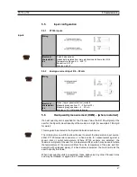
Page 37: ...the user for the Specific Heat Capacity of the medium in J g K for example 4 186 J g K for water This may also be entered in the System Calculation sub menu The In Output menu will then allow the use...

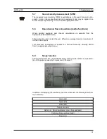
Page 38: ...lation Math menu These allow the user to select the sum difference average mean or maximum of the two flow channels This value may be displayed or applied to a Process Output by selecting MATH from th...

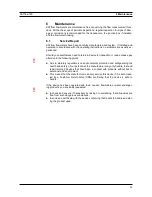
Page 39: ...on to the following points Due to statutory regulations on environmental protection and safeguarding the health and safety of our personnel the manufacturer may only handle test and repair returned de...

Page 40: ...led to write to FRAM Call customer support FRAM READ ERR Hardware Failed to read from FRAM Call customer support RTC ERR Hardware Real Time Clock failure Power on off otherwise call customer support E...

Page 41: ...low SNR Recouple sensors check installation re duce number of passes look for other location then have a cup of tea and call cus tomer support 7 1 Data download difficulties If difficulties are encou...

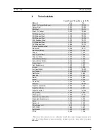
Page 42: ...i 2 060 6 759 Brass Naval 2 120 6 923 Gold hard drawn 1 200 3 937 Inconel 3 020 9 909 Iron electrolytic 3 240 10 630 Iron Armco 3 240 10 630 Ductile Iron 3 000 9 843 Cast Iron 2 500 8 203 Monel 2 720...

Page 43: ...46 C4H9Br 1 276 20 C 1 019 20 C 3 343 2 68 F 0 49 15 C 5 272 59 C n Butyl chloride 22 46 C4H9Cl 0 887 1 140 3 740 2 4 57 0 529 15 C 5 692 59 F Carbon tetrachloride CCl4 1 595 20 C 926 3038 1 2 48 0 6...

Page 44: ...0 78 20 C 1 222 20 C 4 009 2 68 F 2 Propanol C3H8O 0 785 20 C 1 170 20 C 3 838 6 68 F 2 718 29 245 Propene C3H6 0 563 13 C 963 13 C 3159 4 9 F 6 32 n Propyl alcohol C3H8O 0 78 20 C 1 222 20 C 4 009 2...

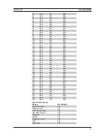
Page 45: ...4 7 2 4 1 00 10 76 Water heavy D2O 1 400 4 593 Water sea 1 025 1531 5023 2 4 1 00 10 76 Temperature Sound Speed in Water C F m s ft s 0 32 0 1402 4600 1 33 8 1407 4616 2 35 6 1412 4633 3 37 4 1417 464...

Page 46: ...131 0 1547 5076 56 132 8 1548 5079 57 134 6 1548 5079 58 136 4 1548 5079 59 138 2 1550 5086 60 140 0 1550 5086 61 141 8 1551 5089 62 143 6 1552 5092 63 145 4 1552 5092 64 147 2 1553 5092 65 149 0 1553...

Page 47: ...3 149 300 0 1465 4807 154 310 0 1453 4767 160 320 0 1440 4725 166 330 0 1426 4679 171 340 0 1412 4633 177 350 0 1398 4587 182 360 0 1383 4538 188 370 0 1368 4488 193 380 0 1353 4439 199 390 0 1337 438...

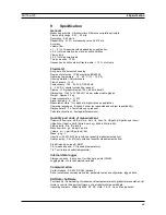
Page 48: ...sh 2 other as requested and subject to availability Response time 1 s faster rates upon request Calculation functions Average difference sum Quantity and units of measurement Volumetric flow rate m3 h...

Page 49: ...130 C 22 266 F Type K1E 30 250 C 22 482 F for short periods up to 300 C 572 F Degree of protection IP 66 acc EN 60529 IP 67 and IP 68 optional Type K4L K4N K4E Diameter range 10 250 mm Dimensions 43...

Page 50: ...Scope function 38 Disturbance sources 11 Sensor configuration 13 Dual channel calculations 38 Sensor Location 10 Dual channel display mode 27 Sensor mounting 17 Electrical connections 16 Sensor mount...

Page 51: ...KATflow 150 Appendix A Appendix A Certificate of Conformity 51...

Page 52: ...g environment please Nuclear radiation Water endangering Toxic Caustic Biological Other please specify We confirm delete if not applicable that we have checked the instrument and sensors are free of a...

Reviews: