Dokument
IMA 212
Rev
1
Page
2 (4)
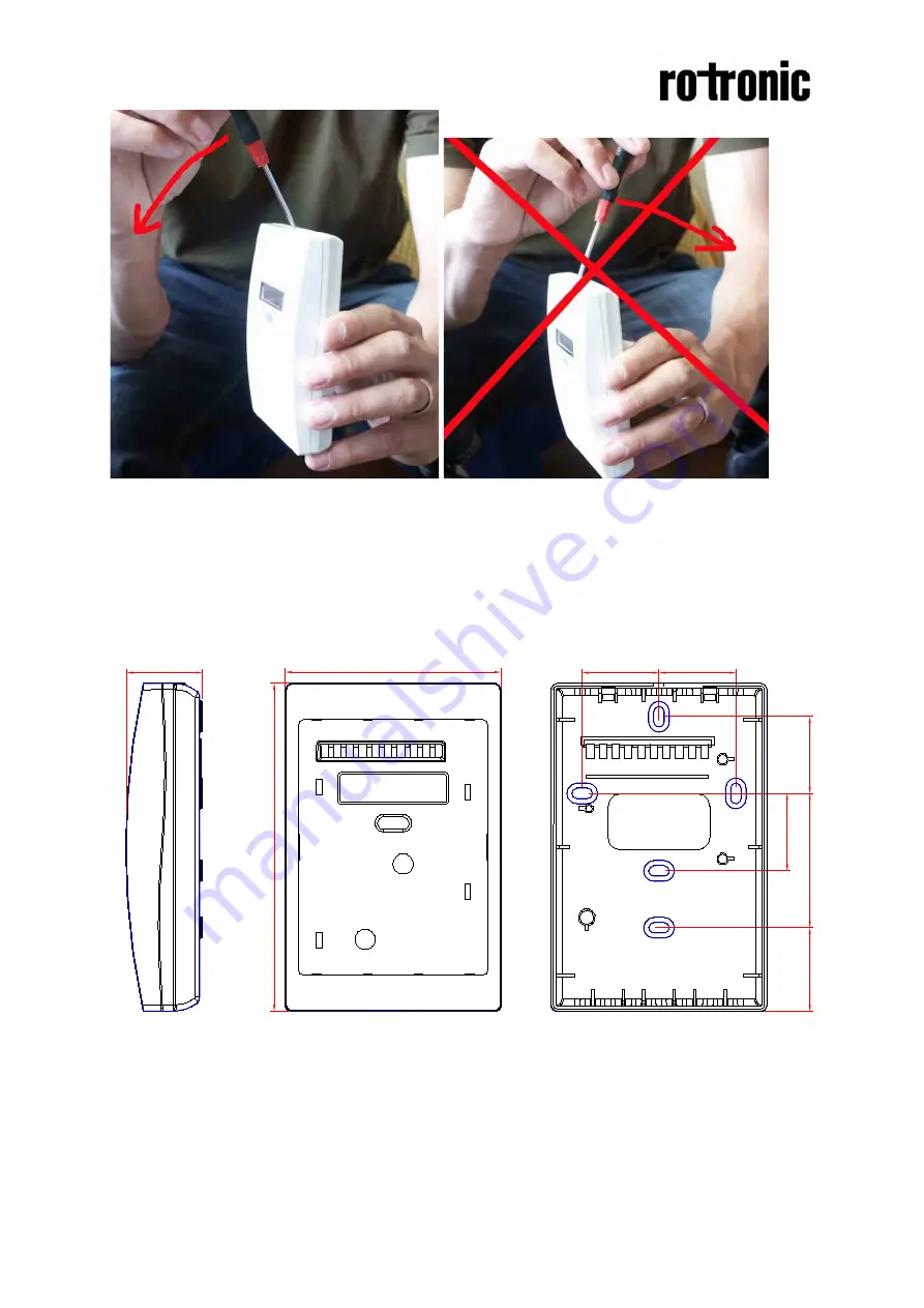
Figure 2. Closed housing seen from the side. Figure 3. Closed housing seen from the side.
The housing is opened by inserting a screw
Never push to the right. The locking hooks
driver and pushing left (to the front side).
may break and the housing is damaged
The locking hooks will then be released.
Dimensions
Figure 3. The dimensions of the sensor in mm and (inches)
128,4(5,06
)
85(3,34)
32,7(1,29)
30(1,18)
30(1,18)
30(1,18)
30(1,18)
52,5(2,07)
30(1,18)


