EXPLORER 122
User Manual
98-150578-A
A-6
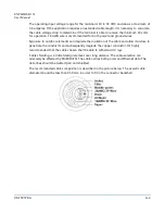
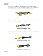
The bare ends on the stripped wire may require twisting to prevent fraying when the
connector parts are slid over the cable. Slide the items over the cable in sequential order as
shown in Figure A-2. Observe that the seal ring and red gasket are present.
Figure A-2. Connector Part Description
Apply a thin coat of solder for tinning on the bare wires and on the connector socket
contacts in preparation of soldering the wires to the end connector contacts as shown in
Figure A-3. Solder the tinned wires to the socket contacts.
Figure A-3. Cable Assembly - Step 1
Assemble the gasket into the clamp ring. The gasket is directional and the flat surface should
be installed on the housing side as shown in Figure A-4.
Figure A-4. Cable Assembly - Step 2
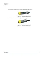
Assemble the clamp ring to the housing as shown in Figure A-5.
Figure A-5. Cable Assembly - Step 3


