1
GETTING STARTED
OPERATION FROM HANDSET cont'd
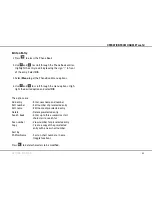
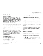
Idle mode
When.in.idle.mode.the.ISDN.Handset.displays:
The.signal.strength.indicator.indicates.maximum.signal.
strength.by.all.segments.shown.dark.
When.the.terminal.is.busy,.the.status.line.indicates.the.type.
of.service.in.use.(indicated.on.all.ISDN.Handsets.connected.to.
the.terminal):
4.8k.speech.
-.ongoing.low.cost.voice.call
Fax.call.....
-.ongoing.fax.call
Data.
.
-.ongoing.data.call
MPDS.call....
-.ongoing.MPDS.call
SAILOR 33 Fleet+ Start-up
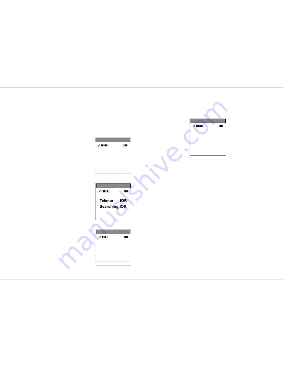
At.start-up.SAILOR.33.Fleet+.performs.system.initialization.
and.then.search.for.a.satellite.(expect.a.wait.of.about.30.
seconds.after.power.on).
Note!
The Ocean Region used the last
time the system was in operation
will be searched for.
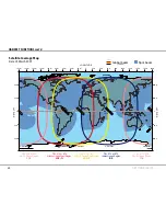
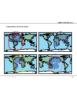
Available.Ocean.Regions:
Atlantic.Ocean.Region.East.(AOR-E)
Atlantic.Ocean.Region.West.(AOR-W)
Indian.Ocean.Region.(IOR)
Pacific.Ocean.Region.(POR)
After.completed.the.start-up.sequence
the.SAILOR.33.Fleet+.enters.idle.mode.
See.
Satellite Search
.in.the.HANDSET.
FUNCTIONS.section.on.how.to.initiate.a.
manual.search..
If.required,.see.
Select Default Net
Service Provider
.in.the.HANDSET.FUNC-
TIONS.section..
Note!
If the Access Code feature has been enabled,
an access code must be entered before call-
ing (see Access Control > Access code in the
User Guide).
.
•
•
•
•
Telenor IOR
Ready for call
System MMI
OK Menu
Alarm.indicator
(See
View Alarms
)
Signal.strength
indicator
Ocean.Region
Service.provider
Status.Line
Soft-key.choices
Registering...
Please wait
Information
System MMI
Telenor IOR
Ready for call
System MMI
OK Menu
Summary of Contents for SAILOR 33 Fleet+
Page 1: ...F77 USER MANUAL SAILOR 33 Fleet Getting Started ...
Page 2: ......
Page 7: ... GETTING STARTED INTRODUCTION cont d SAILOR 33 Fleet Antenna Unit Parts ...
Page 28: ...28 GETTING STARTED HANDSET FUNCTIONS cont d Date 15 March 2007 Satellite Coverage Map ...
Page 29: ...29 GETTING STARTED HANDSET FUNCTIONS cont d Coverage Map for Each Ocean Region ...
Page 49: ...A APPENDIX A INSTALLATION cont d GETTING STARTED Connecting up ...
Page 50: ...A APPENDIX A INSTALLATION cont d GETTING STARTED Grounding and strain relief ...
Page 51: ...A APPENDIX A INSTALLATION cont d GETTING STARTED Outline dimensions ...
Page 54: ...A APPENDIX A INSTALLATION cont d GETTING STARTED BDU connectors Rear connector panel ...
Page 61: ...A 16 APPENDIX A INSTALLATION cont d GETTING STARTED Serial printer settings ...
Page 67: ...B GETTING STARTED APPENDIX B1 CONNECTING UP BCSiTA V APPENDIX B CONNECTING UP BCSiTA ...
Page 72: ......
Page 73: ......


