Functional description
Functional description
Functional description
Functional description
Installation - TT-3020C
Installation - TT-3020C
Installation - TT-3020C
Installation - TT-3020C
25-Jul-00
25-Jul-00
25-Jul-00
25-Jul-00
Page
Page
Page
Page 2-5
2-5
2-5
2-5
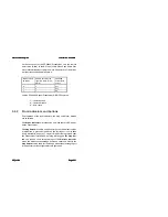
on the rear panel of the TT-3020C Transceiver, and the remote
on/off wire (white) in the DC input cable. Please see Table 5 for
more information about remote on/off. The priority of the differ-
ent functions are defined in Table 4.
Master on/off
switch S1
Remote on/off by the
input DC cable (pin 6,
white)
TT-3020C
Transceiver
on/off
0
x
Off
1
0
Off
1
1
On
Table 4 TT-3020C Capsat Transceiver ON/OFF overview
‘’1’’ - feature active
‘’0’’ - feature disable
‘’x’’ - don’t care
2.4.2
Front indicators and buttons
The functions of the five indicators, the Stop and Alarm buttons
are as follows.
The
Power indicator
will always be on when there is DC-power
on the Transceiver.
The
Stop button
is used to set the serial port to the default values.
If this button is pressed at power-on the serial port is set to 4800
baud, 8 databits, no parity, 1 stopbit. If the button is pressed after
the Transceiver is turned on, nothing will happen. The
Stop but-
ton
can also be used for switching off the
Distress indicator
when the distress acknowledge has been received. Finally the
Stop button
can be used for initiating a manual positioning report
if the transceiver is configured for this operation.


