Installation - TT-3020C
Installation - TT-3020C
Installation - TT-3020C
Installation - TT-3020C
Connectors
Connectors
Connectors
Connectors
Page
Page
Page
Page 2-12
2-12
2-12
2-12
25-Jul-00
25-Jul-00
25-Jul-00
25-Jul-00
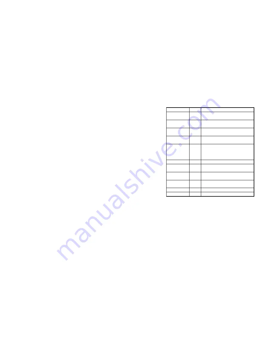
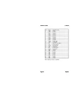
Signal
X4 pin
Specification general purpose I/O
I/O0 (IO)
1
Digital open collector output with pull-
up/input with pull-up (RS-410N).
I/O1 (IO)
2
Digital open collector output with pull-
up/input with pull-up (RS-410N).
I/O2 (IO)
3
Digital open collector output with pull-
up/input with pull-up (RS-410N).
I/O3 (IO)
4
Digital open collector output with pull-
up/input with pull-up (RS-410N).
9Vdc
(O)
5
DC +9V, ±10%. Max. 400mA. Floating
Supply voltage for external devices.
Note: Max. load (400mA) is a combina-
tion of this output and X1 pin 14,15.
Ground
6,9
Ground reference.
ArcNet A/B (IO)
7/8
ArcNet signal wires A/B (ATA/ANSI
878.1; ARCNET/TB).
NMEA Out A/B
10/11
NMEA 0183 output signal wires A/B
(NMEA 0183 version 2.1).
NMEA In A/B
12/13
NMEA 0183 input signal wires A/B
(NMEA 0183 version 2.1).
I4
(I)
14
Digital input with pull-up (RS-410N).
I5
(I)
15
Digital input with pull-up (RS-410N).
Table 8 TT-3020C X4 pin assignment
The I/O connector, a standard DB-15 female connector, is located
on the rear panel of the transceiver and is marked X4.
2.5.3.1
NMEA 0183 Reception
The NMEA 0183 Standard uses the ASCII alphabet to send strings
containing navigational data. This data can be read by the Trans-
ceiver via the I/O NMEA interface connector X4.
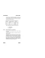
The following is a list of the NMEA codes that the Transceiver will
recognise with or without a built-in GPS.


